
Intelligent anti-smashing barrier gate rod and barrier gate using same

A barrier gate and anti-smashing technology, which is applied to the field of barrier barriers and barrier gates using the barrier gates, can solve the problems of long construction period, increase user cost, and affect the appearance of the road surface, so as to avoid smashing Accidents caused by cars smashing into people, wide application range

Pending Publication Date: 2021-10-22
JIANGXI BAISHENG GATE & DOOR AUTOMATION
View PDF0 Cites 0 Cited by
  • Summary
  • Abstract
  • Description
  • Claims
  • Application Information

AI Technical Summary

Problems solved by technology

Due to the widespread use of barrier gates, the phenomenon of smashing vehicles during the descent of barrier gates has also increased. At present, most of the gate levers on the market to prevent vehicles from smashing people use anti-collision rubber strips, infrared, ground sense, etc. However, the sensitivity of anti-collision rubber strips is slightly poor, infrared, ground sense, etc. are installed as auxiliary products of barrier gates, which increases the user's cost of use; ground sense also needs to excavate the ground to install coils, and the construction period is long, affecting the appearance of the road surface and Only works on vehicle collision avoidance

Method used


Image

  • Intelligent anti-smashing barrier gate rod and barrier gate using same
  • Intelligent anti-smashing barrier gate rod and barrier gate using same
  • Intelligent anti-smashing barrier gate rod and barrier gate using same

Examples


Embodiment Construction

[0029] It should be noted that in this embodiment, the descriptions of the orientation words "up", "down", "left", "right", and "horizontal" are all described according to the drawings, and do not constitute a limitation to the present invention .

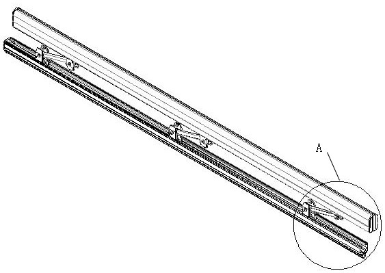
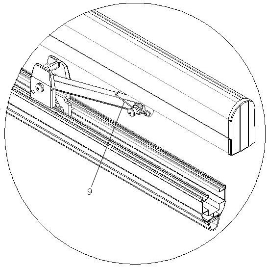
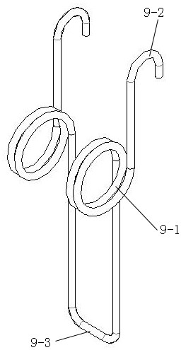
[0030] Attached below Figure 1-10 The present invention is further described in detail: a barrier using an intelligent anti-smashing barrier bar, including a barrier gate chassis 10, a barrier bar splint 11 and an intelligent anti-smashing barrier bar; Figure 6 As shown, the barrier bar splint 11 is installed on the barrier gate core, and the barrier gate core is installed in the barrier gate chassis 10 as the power output device of the barrier gate; the intelligent anti-smashing barrier gate lever includes the main beam 1, the connecting rod joint seat 2. Travel switch 3, connecting rod end handle 4, connecting rod 5, rotating shaft pin 6, sub-beam 7 and limit part, one end of main beam 1 is fixed with barrier bar splint 11, an...


PUM


Abstract

The invention relates to an anti-smashing barrier gate rod and a barrier gate using same. The invention discloses the intelligent anti-smashing barrier gate rod and the barrier gate using the same. The intelligent anti-smashing barrier gate rod comprises a limiting part, a connecting rod, a sensor, a main beam and an auxiliary beam, wherein the main beam and the auxiliary beam are parallel with each other; the limiting part is installed on the main beam and / or the auxiliary beam and provides pre-tightening force for the connecting rod to limit the connecting rod from rotating in the length direction of the main beam or the auxiliary beam to press the sensor; the connecting rod is obliquely arranged between the main beam and the auxiliary beam, two ends of the connecting rod are rotatably connected with the main beam and the auxiliary beam respectively, and one end of the connecting rod is provided with a handle; the sensor is mounted on the main beam or the secondary beam close to the handle; the main beam is connected with a power output shaft of the barrier gate; when the auxiliary beam touches an obstacle and forces the connecting rod to rotate in the length direction of the main beam and the auxiliary beam, the handle presses the sensor switch to enable the sensor to send a signal to the controller, and when the controller receives the signal sent by the sensor, the controller controls the barrier to lift the rod. The anti-smashing barrier gate rod has the following advantages: 1, the application range is wide; and 2, the accident that the brake bar hits a car and a person is avoided.

Description

technical field [0001] The invention relates to an anti-smashing barrier bar and a barrier gate using the same, in particular to a barrier gate for parking lots, entrances and exits of residential areas, toll stations, schools, etc., which can avoid accidental injury to people or vehicles Bars and gates. Background technique [0002] As an important supporting product of smart cities, barrier gates are widely used in the import and export of companies, communities, and schools. Due to the widespread use of barrier gates, the phenomenon of smashing vehicles during the descent of barrier gates has also increased. At present, most of the gate levers on the market to prevent vehicles from smashing people use anti-collision rubber strips, infrared, ground sense, etc. However, the sensitivity of anti-collision rubber strips is slightly poor, infrared, ground sense, etc. are installed as auxiliary products of barrier gates, which increases the user's cost of use; ground sense also...

Claims


Application Information

Patent Timeline
Patent Type & Authority Applications(China)
IPC IPC(8): E01F13/06
CPCE01F13/06
Inventor 刘润根
Owner JIANGXI BAISHENG GATE & DOOR AUTOMATION
Learn More