Test tool structure for verifying pressure of special-shaped spray pipe

A nozzle pressure and tester technology, which is used in the testing of mechanical parts, jet engine testing, machine/structural parts testing, etc. problems, to achieve the effect of meeting the test pressure load conditions and reducing the flow capacity requirements

Active Publication Date: 2021-10-22
中国航发贵阳发动机设计研究所
View PDF12 Cites 0 Cited by
  • Summary
  • Abstract
  • Description
  • Claims
  • Application Information

AI Technical Summary

Problems solved by technology

The special-shaped nozzle has good stealth comprehensive performance, but its aerodynamic pressure bearing capacity is poor. In order to verify whether the structural design of the special-shaped nozzle meets the requirements for strength and use, it is necessary to carry out a special-shaped casing pressure test to ensure the rationality of the design.
[0003] For the strength test of special-shaped nozzles, the conventional pressure test method is to fixedly connect the transition section at both ends of the typical casing, and form a closed cavity with the casing for loading. However, due to the particularity of the nozzle installation constraint structure (nozzle Unconstrained at the outlet end) and the non-uniformity of the wall load along the nozzle, the use of conventional pressure test tooling structure will inevitably bring greater uncertainty to the test results; Higher, requiring higher air flow to meet test pressure loading conditions

Method used


Image

  • Test tool structure for verifying pressure of special-shaped spray pipe
  • Test tool structure for verifying pressure of special-shaped spray pipe
  • Test tool structure for verifying pressure of special-shaped spray pipe

Examples


Embodiment Construction

[0025] The following will clearly and completely describe the technical solutions in the embodiments of the present invention with reference to the accompanying drawings in the embodiments of the present invention. Obviously, the described embodiments are only part of the embodiments of the present invention, not all of them. Based on the embodiments of the present invention, all other embodiments obtained by persons of ordinary skill in the art without creative efforts fall within the protection scope of the present invention.

[0026] It should be noted that all directional indications (such as up, down, left, right, front, back...) in the embodiments of the present invention are only used to explain the relationship between the components in a certain posture (as shown in the accompanying drawings). Relative positional relationship, movement conditions, etc., if the specific posture changes, the directional indication will also change accordingly.

[0027] In addition, the ...


PUM


Abstract

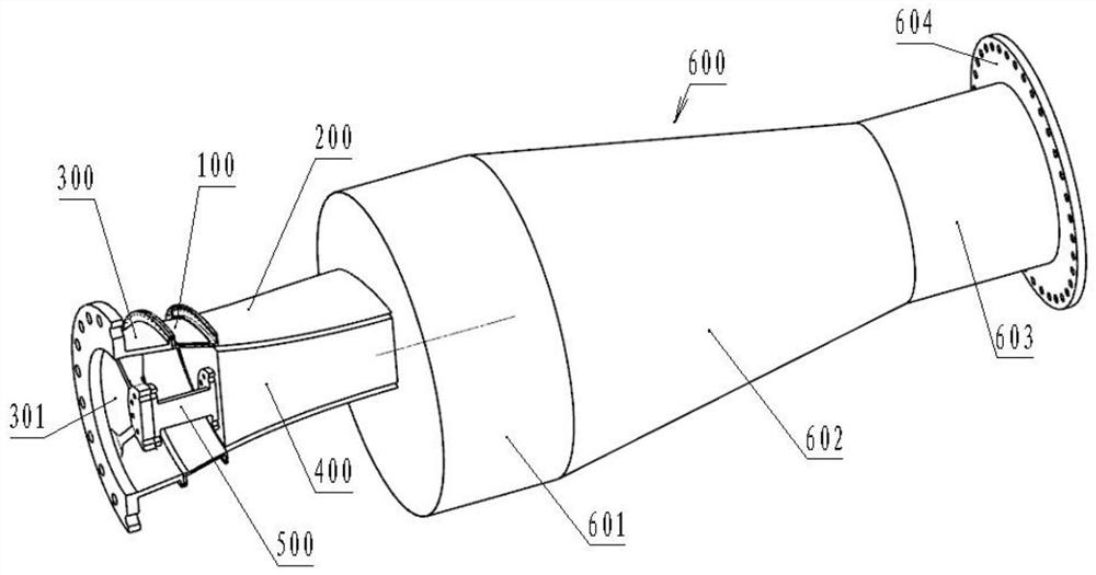
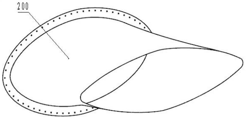
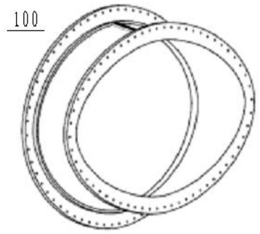
A test tool structure for verifying the pressure of a special-shaped spray pipe comprises an analog casing and a spray pipe connected to the air outlet end of the analog casing, and a mandrel is arranged in the spray pipe; a gap is formed between the outer surface of the mandrel and the inner surface of the spray pipe to form an annular flow channel; the air inlet end of the simulation casing is provided with an adapter ring used for being connected with a tester air source pipeline; an air source inlet is formed in the adapter ring; and the left end of the mandrel is fixedly connected to the adapter ring through a supporting column. According to the invention, the spray pipe is directly connected to the simulation casing for testing, the mandrel is arranged in the spray pipe, the annular flow channel for airflow circulation is formed according to an equal-area change rule, and test load loading is carried out on the spray pipe through the annular flow channel, so that the actual working state of the spray pipe can be truly simulated; and meanwhile, the requirement on the flow capacity of the tester is reduced, and the test pressure load condition can be met by adopting relatively low air flow.

Description

technical field [0001] The invention relates to the technical field of pressure testing of special-shaped nozzles of aero-engines, in particular to a test fixture structure for verifying the pressure of special-shaped nozzles. Background technique [0002] Aeroengine nozzle is the main component of the engine, and its structural design reliability is closely related to the reliability of the entire engine. The special-shaped nozzle has good stealth comprehensive performance, but its aerodynamic pressure bearing capacity is poor. In order to verify whether the structural design of the special-shaped nozzle meets the requirements of strength and use, it is necessary to carry out a special-shaped casing pressure test to ensure the rationality of the design. [0003] To carry out the special-shaped nozzle strength test, the conventional pressure test method is to fixedly connect the transition section at both ends of the typical casing, and form a closed cavity with the casing t...

Claims


Application Information

Patent Timeline
Patent Type & Authority Applications(China)
IPC IPC(8): G01M13/00G01M15/14
CPCG01M13/00G01M15/14
Inventor 邓洁李环黄标周公铜杜凯
Owner 中国航发贵阳发动机设计研究所
Why Eureka
Try Eureka