
Laser radar system and driving equipment

A lidar and radar technology, applied in the field of lidar systems and driving equipment, can solve the problems of long detection distance of laser beam and undetectable area.

Pending Publication Date: 2021-10-22
LEISHEN INTELLIGENT SYST CO LTD
View PDF0 Cites 0 Cited by
  • Summary
  • Abstract
  • Description
  • Claims
  • Application Information

AI Technical Summary

Problems solved by technology

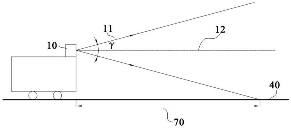
However, for a multi-line lidar with a small vertical field of view, the detection distance of its laser beam is relatively long, resulting in the short-distance area around the multi-line lidar being unable to be detected, and there is a short-range detection blind spot

Method used


Image

  • Laser radar system and driving equipment
  • Laser radar system and driving equipment
  • Laser radar system and driving equipment

Examples


Embodiment Construction

[0041] Embodiments of the present application are described in detail below, examples of which are shown in the drawings, wherein the same or similar reference numerals denote the same or similar elements or elements having the same or similar functions throughout. The embodiments described below by referring to the figures are exemplary, and are only for explaining the present application, and should not be construed as limiting the present application.

[0042] In the description of the present application, it should be understood that the terms "center", "longitudinal", "transverse", "length", "width", "thickness", "upper", "lower", "front", " Back", "Left", "Right", "Vertical", "Horizontal", "Top", "Bottom", "Inner", "Outer", "Clockwise", "Counterclockwise", "Axial" , "radial", "circumferential" and other indicated orientations or positional relationships are based on the orientations or positional relationships shown in the drawings, and are only for the convenience of de...


PUM


Abstract

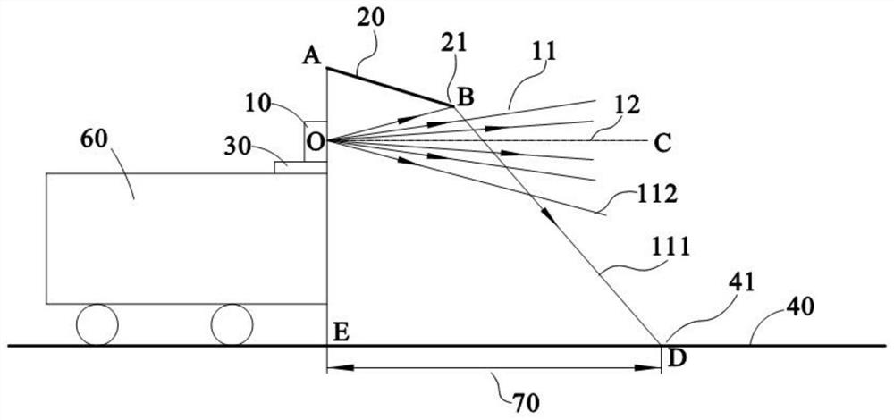
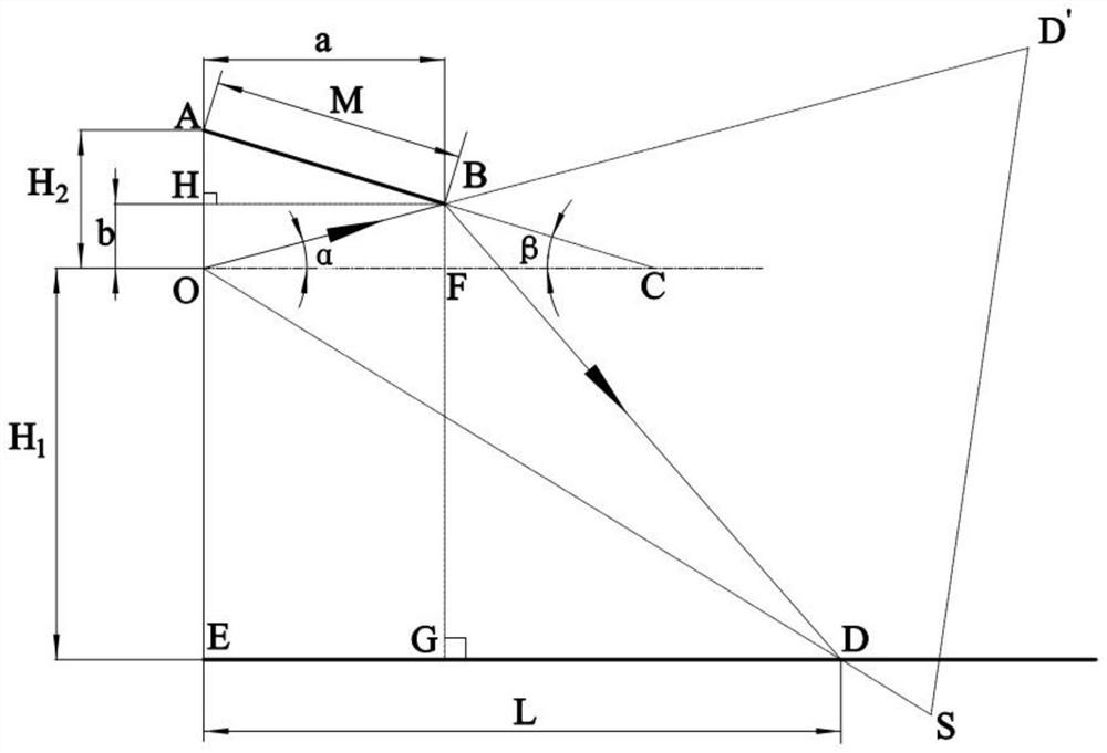
The invention discloses a laser radar system and driving equipment, and relates to the technical field of laser radars. The laser radar system comprises a multi-line laser radar and a reflecting plate, and the multi-line laser radar is used for emitting a plurality of laser beams; the reflecting plate is arranged on one side, deviating from a to-be-detected plane, of the multi-line laser radar, and is used for reflecting at least one target laser beam located on one side, deviating from the to-be-detected plane, of an optical axis of the multi-line laser radar to the to-be-detected plane, the detection distance corresponding to at least one target laser beam is smaller than or equal to a preset obstacle avoidance distance, and the at least one target laser beam is an edge laser beam. The laser radar system provided by the invention can realize short-distance obstacle avoidance and reduce a detection blind area.

Description

technical field [0001] The present application relates to the technical field of laser radar, in particular to a laser radar system and driving equipment. Background technique [0002] At present, the optical axis of the multi-line lidar is usually set parallel to the horizontal direction, and the offset of the vertical field of view is set to 0 degrees. However, for a multi-line lidar with a small vertical field of view, the detection distance of its laser beam is relatively long, resulting in the short-distance area around the multi-line lidar being unable to be detected, and there is a short-range detection blind spot. Contents of the invention [0003] The application provides a laser radar system and driving equipment to reduce the short-distance detection blind area of ​​the laser radar system and realize short-distance obstacle avoidance. [0004] This application provides: [0005] A lidar system comprising: [0006] multi-line lidar for emitting multiple laser ...

Claims


Application Information

Patent Timeline
IPC IPC(8): G01S17/02G01S17/931
CPCG01S17/02G01S17/931
Inventor 胡小波农远峰刘贵荣蓝秋明
Owner LEISHEN INTELLIGENT SYST CO LTD
Learn More