
Battery wiring module and flexible substrate with electronic component

A technology of flexible printing and electronic components, applied in the direction of printed circuits, printed circuits, battery pack components, etc., to achieve the effect of stable protection function

Pending Publication Date: 2021-10-26
AUTONETWORKS TECH LTD +2
View PDF4 Cites 0 Cited by
  • Summary
  • Abstract
  • Description
  • Claims
  • Application Information

AI Technical Summary

Problems solved by technology

[0005] When the vehicle is placed in a high-humidity environment, etc., there is a possibility that the FPC constituting the battery wiring module will condense

Method used


Image

  • Battery wiring module and flexible substrate with electronic component
  • Battery wiring module and flexible substrate with electronic component
  • Battery wiring module and flexible substrate with electronic component

Examples


Embodiment approach 1

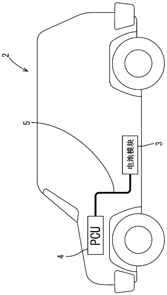
[0046] refer to Figure 1 to Figure 5 Embodiment 1 will be described. A flexible printed circuit board with a current limiting element (hereinafter simply referred to as "FPC with a current limiting element") 1 of this embodiment is used for a battery module 3 mounted in a vehicle 2 such as an electric vehicle or a hybrid vehicle.

[0047] Such as figure 1 As shown, the battery module 3 is disposed near the center of the vehicle 2 . A PCU (Power Control Unit) 4 is arranged at the front of the vehicle 2 . The battery module 3 and the PCU 4 are connected by a wire harness 5 . The battery module 3 has a plurality of power storage elements 6 . The power storage element 6 may be a secondary battery such as a nickel-metal hydride secondary battery or a lithium-ion secondary battery, or may be a capacitor.

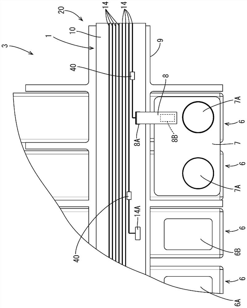
[0048] (battery module 3)

[0049] Such as figure 2 As shown, each storage element 6 is in the shape of a flat rectangular parallelepiped, accommodates a storage element ...

Embodiment approach 2

[0081] Next, refer to Figure 6 and Figure 7Embodiment 2 will be described. As in the first embodiment, the FPC 50 with a current limiting element of this embodiment is used for the battery module 3 . The FPC 50 with a current limiting element is different from the first embodiment in that the surface of the cover film 53 of the FPC 51 has a laminated structure 56 (corresponding to a limiting portion and a limiting protrusion) protruding from other parts. The same reference numerals are assigned to the same configurations as those in Embodiment 1 in this embodiment, and description thereof will be omitted.

[0082] Such as Figure 6 As shown, the FPC 50 with a current limiting element includes an FPC 51 , a current limiting element 30 mounted on the FPC 51 , and an insulating element covering portion 57 covering the current limiting element 30 .

[0083] Such as Figure 7 As shown, the FPC 51 includes an insulating base film 11, a conductive path 14 and two regulation li...

Embodiment approach 3

[0097] Next, refer to Figure 8 and Figure 9 Embodiment 3 will be described. As in the first embodiment, the FPC 60 with a current limiting element of this embodiment is used for the battery module 3 . The FPC 60 with a current limiting element differs from the first embodiment in that the FPC 61 includes a substrate main body 62 and a laminated portion 66 (corresponding to a restricting portion and a restricting protrusion) overlapping the substrate main body 62 . The same reference numerals are assigned to the same configurations as those in Embodiment 1 in this embodiment, and description thereof will be omitted.

[0098] Such as Figure 8 As shown, the FPC 60 with a current limiting element includes an FPC 61 , a current limiting element 30 mounted on the FPC 61 , and an insulating element covering portion 67 covering the current limiting element 30 .

[0099] Such as Figure 9 As shown, the FPC 61 includes a substrate main body 62 and a lamination portion 66 . The ...


PUM


Abstract

A flexible substrate with an electronic component, comprising: a flexible substrate comprising a conduction path; an electronic component mounted to the flexible substrate and connected to the conduction path; a covering section that covers a connection section between the electronic component and the conduction path; and a restricting section arranged along the outer edge of the covering section. The flexible substrate has a groove arranged along the outer edge of the covering section. The groove has a pair of groove side surfaces. The groove side surface on the far side from the electronic component, out of the pair of groove side surfaces, forms the restricting section.

Description

technical field [0001] The technology disclosed by this specification relates to a flexible printed circuit board with electronic components and a battery wiring module. Background technique [0002] In battery modules for electric vehicles and hybrid vehicles, many cells are connected in parallel to increase output. A plurality of single cells are connected in series or in parallel by connecting electrode terminals of adjacent single cells with connecting members such as bus bars. [0003] A voltage detection line for detecting the voltage of the cells is attached to each connecting member. A battery wiring module is constituted by each connection member and a voltage detection line (corresponding to wiring). [0004] In addition, it is known to connect electronic components such as a current limiting element to a voltage detection line formed on an FPC (flexible printed circuit board). [0005] For example, when the vehicle is placed in a high-humidity environment, dew ...

Claims


Application Information

Patent Timeline
Patent Type & Authority Applications(China)
IPC IPC(8): H05K1/02H05K3/28
CPCY02E60/10H01M2220/20H01M50/249H01M50/569H01M50/284H01M50/209H01M50/204H05K1/0263H05K1/189H05K3/284H05K2201/10181B60R16/0207H01M10/425H01M10/482H01M2200/103H05K1/028H05K3/28H05K2201/10621
Inventor 高桥秀夫高濑慎一
Owner AUTONETWORKS TECH LTD
Learn More