Check patentability & draft patents in minutes with Patsnap Eureka AI!

Patient lower limb load bearing device for CT examination

A technology for lower extremities and patients, which is applied to the field of lower extremity weight-bearing devices for patients, can solve problems such as low work efficiency, single measurement, and inability to scan leg shapes, and achieve the effects of reducing the use of straps, improving accuracy, and having a compact and novel structure.

Inactive Publication Date: 2021-11-05
尹德军
View PDF1 Cites 0 Cited by
  • Summary
  • Abstract
  • Description
  • Claims
  • Application Information

AI Technical Summary

Problems solved by technology

CT scanning can reveal this relationship, but due to the design characteristics of the CT machine, the person must lie down to perform the inspection, which means that these inspections are carried out in a non-weight-bearing state and cannot achieve the effect of fully scanning the bone state; patent "CN112472115A" proposes "a patient's lower limb load-bearing device for CT examination", which is worn on the patient's waist, and the leg restraint belt is bound by bonding the surface of the leg Velcro belt and the parent surface of the leg Velcro belt On the patient's thigh, finally lie on the CT machine and step on the pedal with the foot, under the reaction force of the elastic rope or spring, the patient's leg is in a weight-bearing state, so as to realize the CT examination of the patient's leg under the weight-bearing state; Although the purpose of carrying weight on the legs has been achieved, the weight of the load can only be measured in a single way, and the shape of the legs under different load states cannot be scanned. The use is limited, and when worn on the body, multiple connecting belts are disassembled after inspection. Therefore, It cannot be used in hospitals with a large number of patients, and the work efficiency is too low; in order to meet the above needs, we propose a patient lower limb weight-bearing device for CT examination

Method used


Image

  • Patient lower limb load bearing device for CT examination
  • Patient lower limb load bearing device for CT examination
  • Patient lower limb load bearing device for CT examination

Examples


Embodiment 1

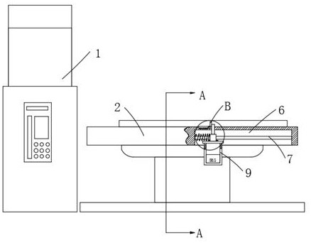
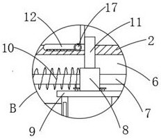
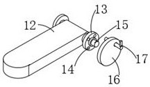
[0024] Such as figure 1 As shown, the patient’s lower limb load-bearing device for CT examination proposed by the present invention includes a CT equipment body 1, a moving bed 2 is provided on one side of the CT equipment body 1, and an adjustment groove 6 is opened on the bottom of the moving bed 2. The adjustment groove 6 A guide rod 7 is fixed inside, refer to figure 2 As shown, the guide rod 7 is covered with a guide sleeve 8, the bottom of the guide sleeve 8 is connected with a load box 9, the top of the guide sleeve 8 is provided with a moving rod 11, and one side of the moving rod 11 screen is provided with a pedal 12 The inner wall of one end of the pedal 12 is provided with a fixed shaft 13, one side of the fixed shaft 13 is rotatably connected with a fixed rod 15, one side of the fixed rod 15 is fixed with a fixed plate 16, and the fixed plate 16 is penetrated with a mounting rod 17, refer to image 3 Shown, fixed disk 16 is provided with a plurality of installat...

Embodiment 2

[0027] Such as Figure 5 As shown, the patient’s lower limb load-bearing device for CT examination proposed by the present invention, compared with Embodiment 1, this embodiment also includes: a cavity 3 is provided in the moving bed 2, and a connecting belt 4 is provided in the cavity 3, One side concave surface of movable bed 2 is fixedly provided with connecting paste 5, and the two ends of guide rod 7 are fixedly connected with the inwall of adjusting groove 6, and the top of adjusting groove 6 is provided with sliding hole, and moving rod 11 runs through sliding hole and is connected with the inner wall of sliding hole. The inner wall is slidingly connected, the cavity 3 is rotated and installed with a winding shaft, and the connecting belt 4 is wound and connected with the winding shaft, one side of the connecting belt 4 is provided with Velcro, and is bonded with the connecting sticker 5, and one end of the connecting belt 4 is limited in connection As for the position ...


PUM


Abstract

The invention relates to the technical field of medical equipment, in particular to a patient lower limb load bearing device for CT examination. According to the technical scheme, the device comprises a CT equipment body; a movable bed is arranged on one side of the CT equipment body; a cavity is formed in the movable bed; a connecting belt is arranged in the cavity; a connecting paste is fixedly arranged on the concave face of one side of the movable bed; an adjusting groove is formed in the bottom of the movable bed; a guide rod is fixedly installed in the adjusting groove; a guide sleeve is arranged on the guide rod in a sleeving mode; a load bearing box is connected inside the bottom of the guide sleeve; a moving rod is arranged on the top of the guide sleeve; a pedal is arranged on one side of a screen of the moving rod; and a fixed shaft is arranged on the inner wall of one end of the pedal in a penetrating mode. The device is compact and novel in structure; the load weight of a patient can be adjusted, so that leg conditions in different states can be examined, and an examination result is more accurate; the pedal is stored, adjusted and used, so that the use flexibility of CT equipment is improved; and the device is suitable for application and popularization.

Description

technical field [0001] The invention relates to the technical field of medical equipment, in particular to a patient's lower limb weight-bearing device for CT examination. Background technique [0002] CT refers to computerized tomography, which is an auxiliary inspection method that uses X-ray scanning to detect the internal organs of the human body; the relationship between the bones of the patient's legs in three-dimensional space is difficult to evaluate using two-dimensional plain films. CT scanning can reveal this relationship, but due to the design characteristics of the CT machine, the person must lie down to perform the inspection, which means that these inspections are carried out in a non-weight-bearing state and cannot achieve the effect of fully scanning the bone state; patent "CN112472115A" proposes "a patient's lower limb load-bearing device for CT examination", which is worn on the patient's waist, and the leg restraint belt is bound by bonding the surface of...

Claims


Application Information

Patent Timeline
Patent Type & Authority Applications(China)
IPC IPC(8): A61B6/03A61B6/04
CPCA61B6/032A61B6/04A61B6/505
Inventor 尹德军刘志伟
Owner 尹德军
Features
  • R&D
  • Intellectual Property
  • Life Sciences
  • Materials
  • Tech Scout
  • Unparalleled Data Quality
  • Higher Quality Content
  • 60% Fewer Hallucinations
Learn More