Movable incinerator interior cleaning device
A technology for cleaning devices and incinerators, applied in incinerators, combustion types, combustion methods, etc., can solve problems such as insufficient stability, waste of clean water, and inability to completely remove dirt, and achieve the effect of convenient and stable devices
- Summary
- Abstract
- Description
- Claims
- Application Information
AI Technical Summary
Problems solved by technology
Method used
Image

Examples
Example Embodiment
[0035] Example 1
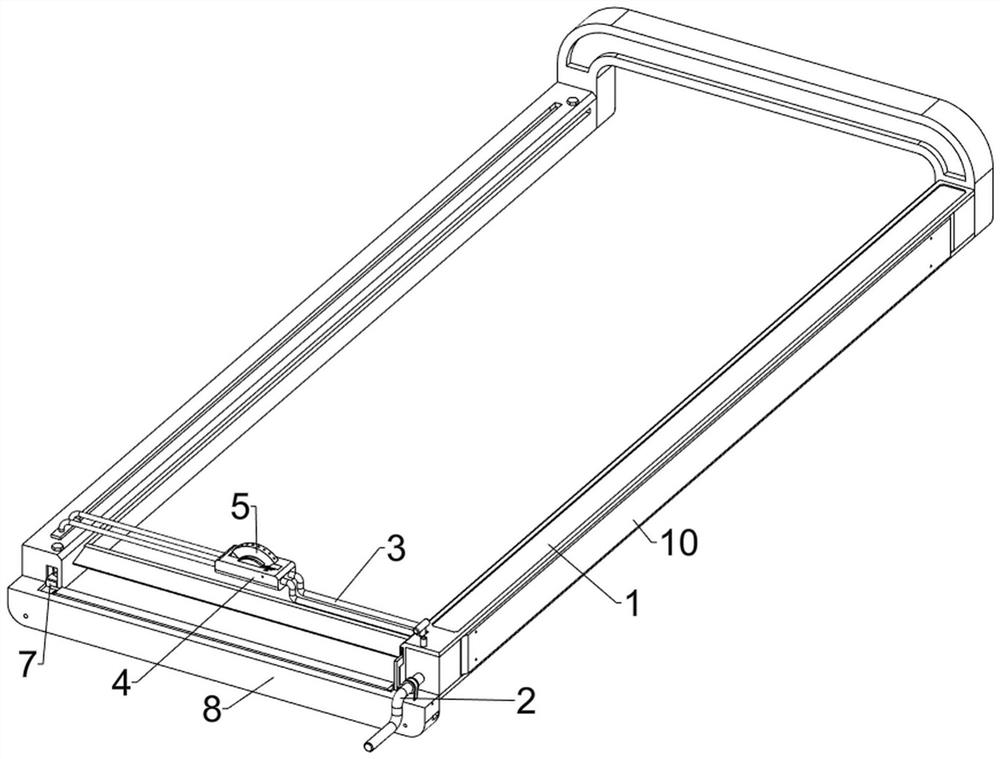
[0036] like Figure 1 ~ 7 As shown, the present embodiment discloses a movable incinerator interior cleaning device including a support seat 1, a moving mechanism 2, a spraying mechanism 3, a rotating mechanism 4, a nozzle 5, and a rotating shaft 6, and a support seat 1 is provided. The mechanism 2, the moving mechanism 2 is provided with a spraying mechanism 3, and a rotating mechanism 4 is provided on the moving mechanism 4, and the rotating mechanism 4 is rotating is provided with a rotating shaft 6, and nozzle 5 is connected to the front side of the rotating shaft 6.
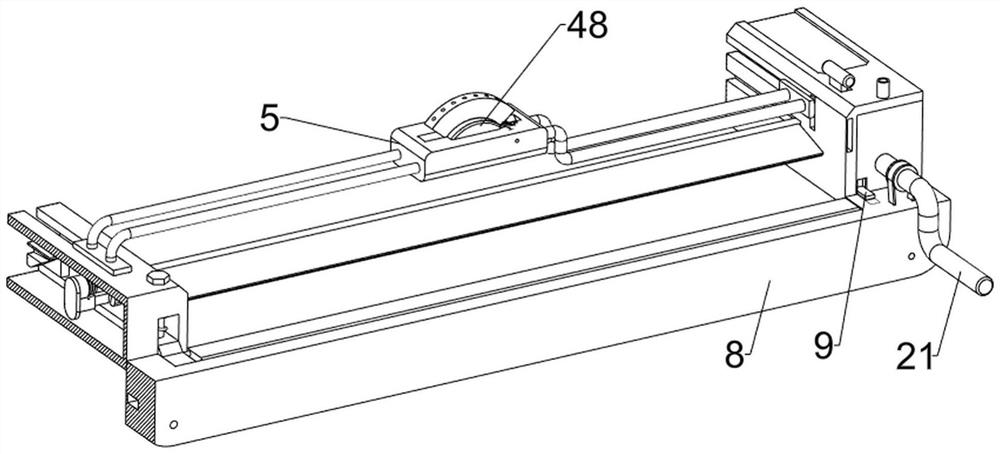
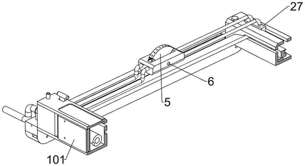
[0037] The moving mechanism 2 includes a transfer 21, a spiral rod 22, a first slider 23, a first conduit 24, a contact rod 25, a link 26, and a second slider 27, and the rotating connection of the support seat 1 right side. The spiral rod 22 is connected to the rotor 21, and the spiral rod 22 is located inside the support seat 1, and the inner sliding connection of the support seat 1 has a fir...
Example Embodiment
[0041] Example 2
[0042] like figure 1 , figure 2 , Figure 8 ~ 17 As shown in some embodiments, it is also included in the cleaning assembly 7, and the cleaning assembly 7 includes a fixing block 71, a second axis 72, a shaped block 73, a torsion spring 74, a scraper 75, a push block 76, a third slider. 77, the second spring 78, the heterogeneous groove 79, the second guide rod 710 and the third spring 711, the lower portion of the first slider 23 and the second slider 27 are connected to the fixed block 71, and the fixed block 71 is rotatable. The second shaft 72, the second shaft 72 is connected to the shaped block 73, and the heterogeneous block 73 is connected between the heterogeneous block 73 and the second shaft 72, the torsion spring 74 is sleeved on the second shaft 72, the front side of the second axis 72 The scraper 75 is connected to the left side of the second shaft 72, and the push block 76 is connected to the lower left side of the shaped block 73, and the third sl...
PUM
 Abstract
Description
Claims
Application Information
 - R&D Engineer
- R&D Manager
- IP Professional
- Industry Leading Data Capabilities
- Powerful AI technology
- Patent DNA Extraction
Browse by: Latest US Patents, China's latest patents, Technical Efficacy Thesaurus, Application Domain, Technology Topic.
© 2024 PatSnap. All rights reserved.Legal|Privacy policy|Modern Slavery Act Transparency Statement|Sitemap