X-ray device

a technology of x-ray and x-ray beam, which is applied in the field of x-ray devices, can solve the problems of affecting the quality of x-ray exposures produced in this way, affecting the access to the patient, and insufficient accuracy of the movement of the robot arms

Inactive Publication Date: 2009-03-10
SIEMENS HEALTHCARE GMBH
View PDF11 Cites 144 Cited by
  • Summary
  • Abstract
  • Description
  • Claims
  • Application Information

AI Technical Summary

Benefits of technology

[0005]An object of the invention is to eliminate the disadvantages inherent in the prior art. The aim is especially to specify an X-ray device which can be produced as simply and inexpensively as possible and ensures improved access to the patient. According to a further objective of the invention, the aim is to increase the degrees of freedom in the movement of the X-ray source and the X-ray detector and therefore create additional diagnostic options.
[0019]A further version provides that two of the proposed X-ray devices can be combined with each other and in fact in such a way that the holders of the two X-ray devices rotate on one and the same rotational axis. In this respect, the X-ray sources or X-ray detectors are arranged with an offset of about 90°. This especially allows complex diagnostic examinations.

Problems solved by technology

Practice has shown, however, that the accuracy of the movements of the robot arms is not always sufficient.
This is detrimental to the quality of the X-ray exposures produced in this way.
Aside from this, the second robot arm attached underneath the patient support also interferes with access to the patient.

Method used


Image

  • X-ray device
  • X-ray device

Examples


Embodiment Construction

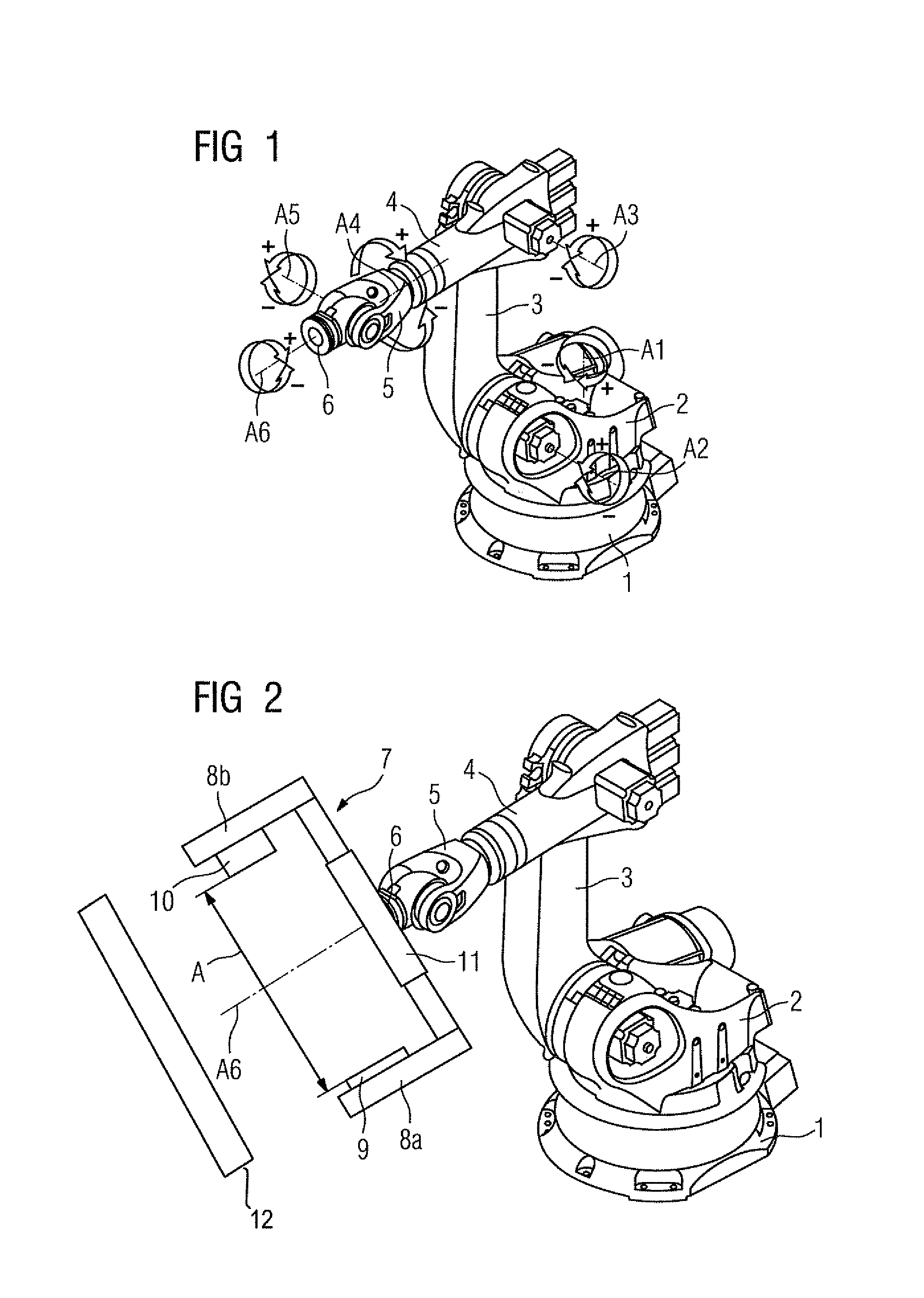
[0023]FIG. 1 shows a robot with six axes of rotation as disclosed according to the prior art. A turntable 2 is mounted on a base frame 1 which is installed permanently on the floor, for example, so as to be capable of rotating about a first axis of rotation A1. A floating link 3 is attached to the turntable 2 so as to be capable of swiveling about a second axis of rotation A2. An arm 4 is fixed to the floating link 3 so as to be capable of rotating about a third axis of rotation A3. A hand 5 is attached to the end of the arm 4 so as to be capable of rotating about a fourth axis of rotation A4. The hand 5 displays a fixing element 6 which is capable of rotating about a rotational axis A6 and swiveling about a fifth axis of rotation A5 running perpendicular to it.

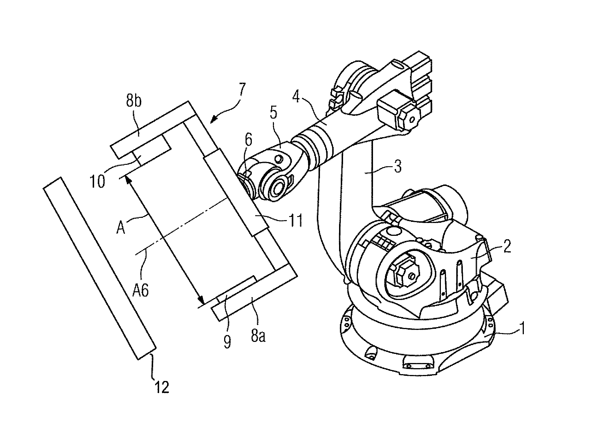
[0024]FIG. 2 shows an embodiment of the invention schematically in a perspective view. A holder generally designated by the reference symbol 7 is connected to the fixing element 6 of the hand 5. A connection not shown in deta...


PUM


Abstract

The invention relates to an X-ray device, in which an X-ray source and an X-ray detector are attached, in an opposed arrangement oriented toward a rotational axis, to a common holder capable of rotating about the rotational axis. To simplify the design of the X-ray device, it is proposed that the holder is attached to the hand of a robot displaying six axes of rotation.

Description

CROSS REFERENCE TO RELATED APPLICATIONS[0001]This application claims priority to the German Application No. 10 2005 012 700.2, filed Mar. 18, 2005 which is incorporated by reference herein in its entirety.FIELD OF INVENTION[0002]The invention relates to an X-ray device.BACKGROUND OF INVENTION[0003]An X-ray device of this type is known for example from DE 199 57 330 A1. The known X-ray device is mounted on a movable trolley. It displays a C-arm fixed in a moveable manner to the trolley, to which C-arm an X-ray source and an X-ray detector are attached in an opposed arrangement. During the use of this X-ray device, in an operating theater for example, the trolley is pushed to an examination table accommodating the patient. Following the production of the X-ray exposure, the trolley is pushed away again to improve access to the patient. Pushing the disclosed X-ray device to and fro is laborious and requires a high level of effort.SUMMARY OF INVENTION[0004]To counteract this disadvantag...

Claims


Application Information

Patent Timeline
Patent Type & Authority Patents(United States)
IPC IPC(8): H05G1/02A61B1/00
CPCA61B6/4441A61B19/2203A61B6/4464B25J9/047A61B6/4458A61B2019/5238A61B6/027A61B2019/5242A61B2090/3764A61B2090/376A61B34/30
Inventor GREBNER, ALBERTKEMETH, HERBERTLURZ, WINFRIEDSCHONBORN, MANFRED
Owner SIEMENS HEALTHCARE GMBH
Why Eureka
Try Eureka