Access systems and methods for minimally invasive surgery

a technology of access systems and minimally invasive surgery, applied in the field of surgical systems and assemblies, can solve the problems of long recovery time, high scarring risk of traditional surgical procedures of this type, and insufficient narrow cannula to perform one-level spinal fixation procedures, so as to improve the field of vision and/or the working space, improve the access to the surgical location, and improve the effect of the surgical location

Inactive Publication Date: 2005-12-08
ZIMMER SPINE INC
View PDF99 Cites 176 Cited by
  • Summary
  • Abstract
  • Description
  • Claims
  • Application Information

AI Technical Summary

Benefits of technology

[0009] Advantageously, in some embodiments the devices as described herein can allow for improved access to a surgical location, such as for performing a procedure on a spinal location. In one embodiment the device can have an expandable distal portion. In one embodiment, the device can have an expandable proximal portion. Expandable portions of the device can provide the operator with an enlarged passage to improve the field of vision and / or the working space within the access device. Moreover, the enlarged passage can allow for multiple instruments to be placed in the passage, with the ability to articulate the instruments at desired angles to reach desired locations in the working space.

Problems solved by technology

Spinal surgery presents significant difficulties to the physician attempting to reduce chronic back pain or correct spinal deformities without introducing additional trauma due to the surgical procedure itself.
Consequently, traditional surgical procedures of this type carry high risks of scarring, pain, significant blood loss, and extended recovery times.
A narrow cannula is typically insufficient to perform one level spinal fixation procedures, which requires visualization of two vertebrae and introduction of screws, rods, as well as other large spinal fixation devices.

Method used


Image

  • Access systems and methods for minimally invasive surgery
  • Access systems and methods for minimally invasive surgery
  • Access systems and methods for minimally invasive surgery

Examples


Embodiment Construction

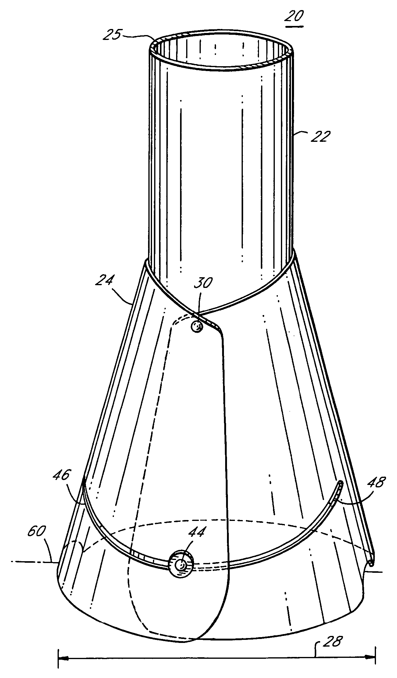
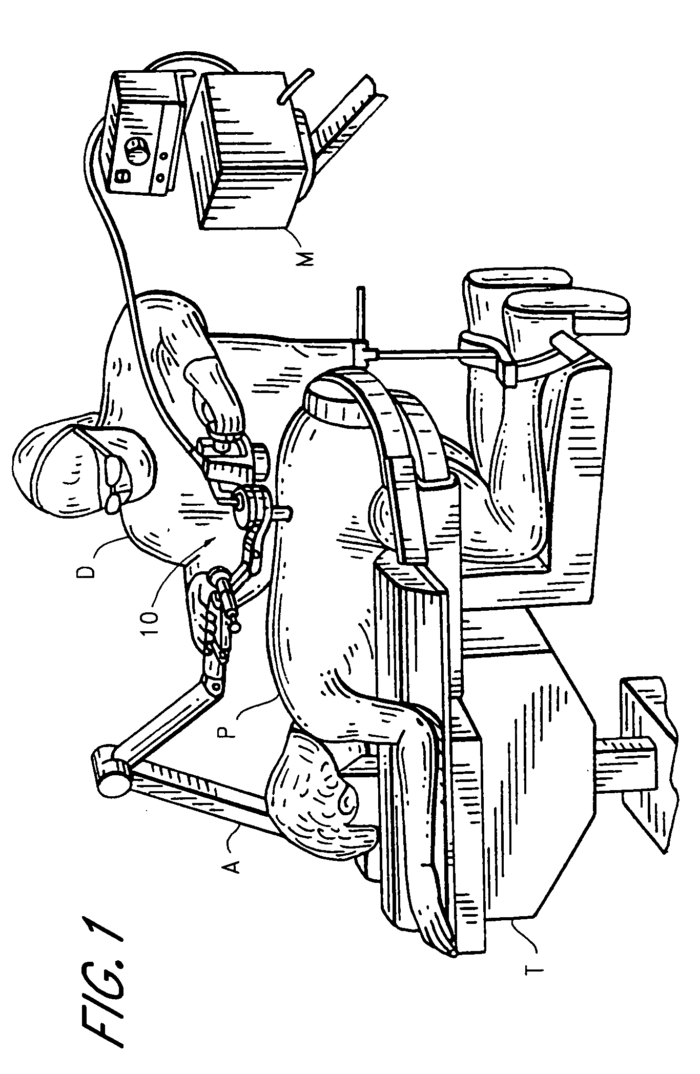
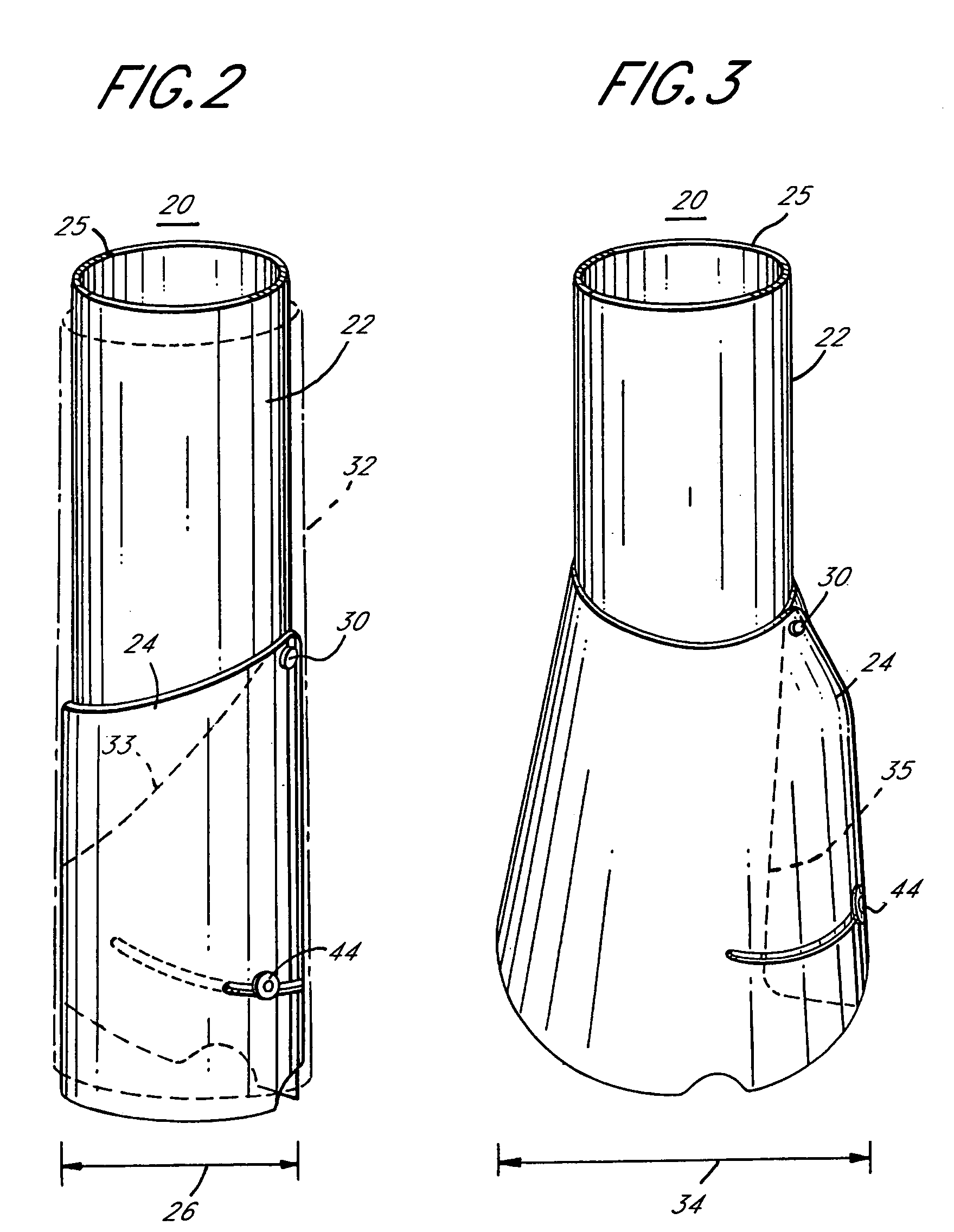
[0315] As should be understood in view of the following detailed description, this application is primarily directed to, though not necessarily limited to, apparatuses and methods for treating the spine of a patient through an access device. More particularly, the systems described below provide access to surgical locations at or near the spine and provide a variety of tools useful in performing treatment of the spine. Also, the systems described herein enable a surgeon to perform a wide variety of methods as described herein.

I. Systems for Performing Procedures at a Surgical Location

[0316] Various embodiments of apparatuses and procedures described herein will be discussed in terms of minimally invasive procedures and apparatuses, e.g., of endoscopic apparatuses and procedures. However, many aspects of the present invention may find use in conventional, open, and mini-open procedures. As used herein, the term “proximal,” as is traditional, refers to the end portion of the appara...


PUM


Abstract

A device for provides access to a surgical location within a patient. The device has an elongate body that has a proximal portion, a distal portion, a first slot segment, and a second slot segment that is angled relative to said first slot segment. The elongate body defines a passage for accessing the surgical location with surgical instruments. The elongate body has a contracted configuration for insertion into the patient and an expanded configuration for providing access to the surgical location. The cross-sectional area of the passage at a first location of the elongate body is greater than the cross-sectional area of said passage at a second location of the elongate body. A movable tab is configured to extend into the second slot segment when the elongate body is in the expanded configuration to retain the elongate body in the expanded configuration.

Description

PRIORITY INFORMATION [0001] This application is based on and claims priority to U.S. Provisional Patent Applications Nos. 60 / 497,822 (filed Aug. 26, 2003), 60 / 497,763 (filed Aug. 26, 2003), 60 / 514,559 (filed Oct. 24, 2003), 60 / 545,587 (filed Feb. 18, 2004), 60 / 579,643 (filed Jun. 15, 2004), and is a continuation-in-part of U.S. patent application Ser. No. 10 / 678,744 (filed Oct. 2, 2003), the entire contents of all of which are hereby expressly incorporated by reference herein.BACKGROUND OF THE INVENTION [0002] 1. Field of the Invention [0003] This application relates to surgical systems and assemblies that include an access device for minimally invasive surgery, and in particular relates to systems and devices that provide access to a surgical location, e.g. adjacent a spine, for one or more instruments to perform a procedure at the surgical location. [0004] 2. Description of the Related Art [0005] Spinal surgery presents significant difficulties to the physician attempting to reduc...

Claims


Application Information

Patent Timeline
Patent Type & Authority Applications(United States)
IPC IPC(8): A61B1/31A61B1/313A61B17/00A61B17/02A61B17/17A61B17/32A61B17/34A61B17/70A61B17/88A61B19/00A61M1/00A61M29/00
CPCA61B1/00149A61B1/00154A61B1/31A61B1/313A61B1/3135A61B17/00A61B17/02A61B17/0218A61B17/1757A61B17/32002A61B17/3403A61B17/3423A61B17/3439A61B17/3462A61B17/7001A61B17/7007A61B17/701A61B17/7032A61B17/7037A61B17/7038A61B17/7041A61B17/7044A61B17/7058A61B17/7082A61B17/7083A61B17/7085A61B17/8875A61B2017/00261A61B2017/00557A61B2217/005A61B2217/007A61B34/70A61B90/30A61B90/361A61B90/50A61B2090/062A61B2090/08021A61B2090/306A61B90/11
Inventor SHLUZAS, ALANDIPOTO, GENELOWERY, GARYKIRK, KARLSTOECKMANN, WALTERROYEN, DONALD
Owner ZIMMER SPINE INC
Why Eureka
Try Eureka