
Implantable drug delivery pump

a technology of implantable drug delivery and pump, which is applied in the direction of pharmaceutical delivery mechanism, infusion device, intravenous device, etc., can solve the problems of less reliable accuracy of drug delivery, less reliable passive drug dispenser in delivering the desired dose than mechanical dispenser, and unsatisfactory side effects of therapeutic agents to targets other than the desired target, etc., to achieve the effect of convenient percutaneous palpation

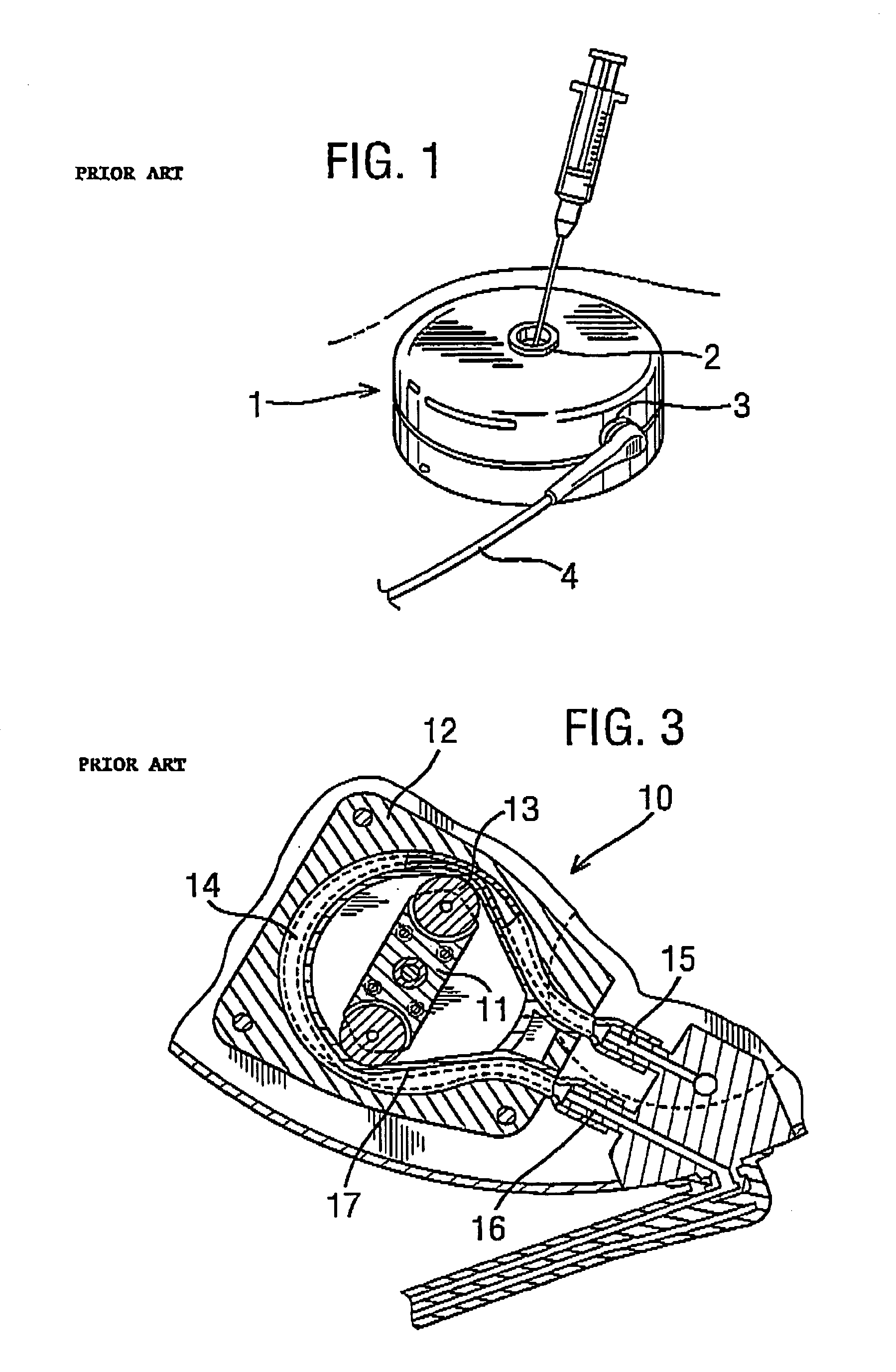
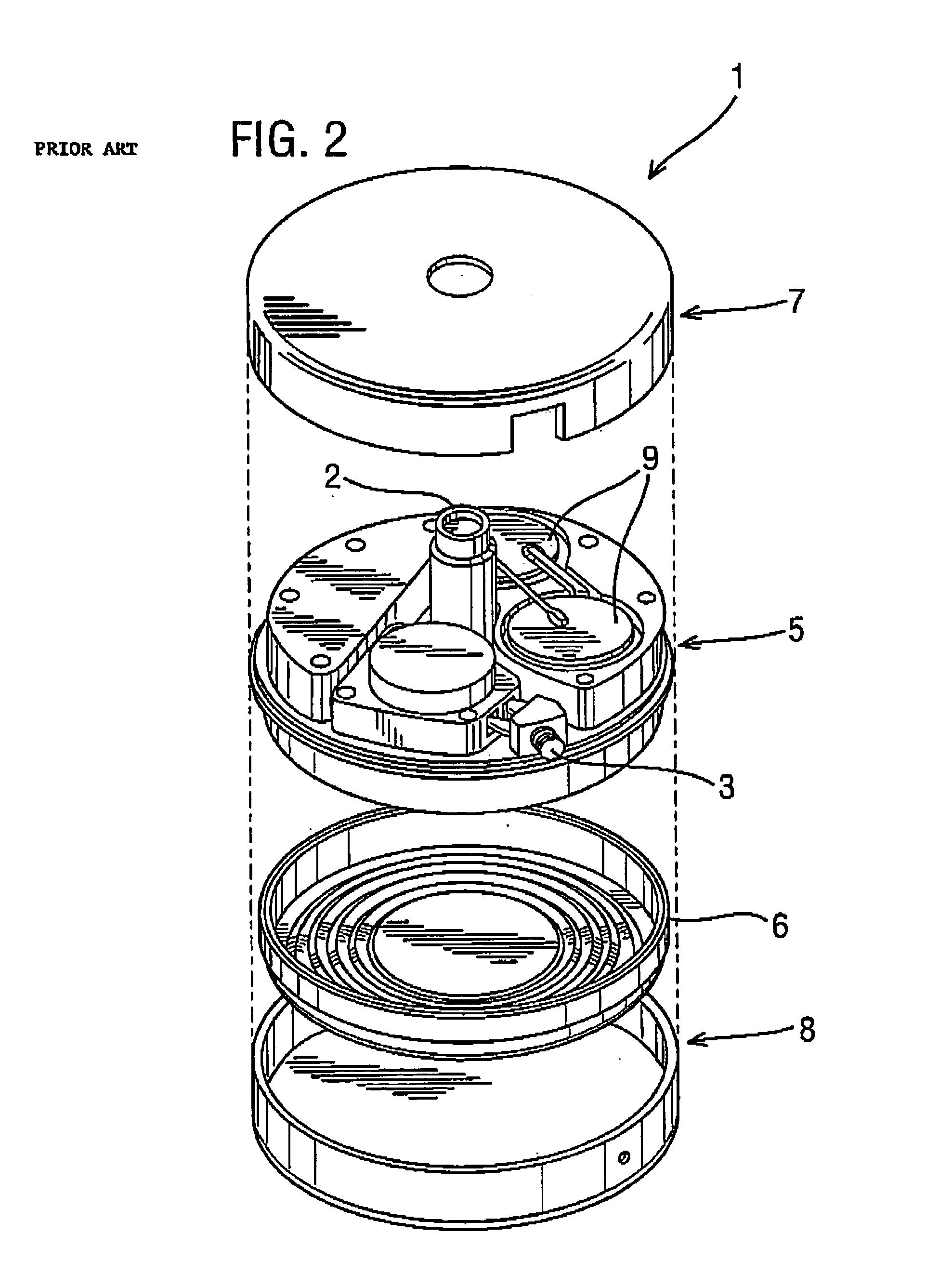
Inactive Publication Date: 2008-03-11
RENISHAW PLC
View PDF38 Cites 188 Cited by
  • Summary
  • Abstract
  • Description
  • Claims
  • Application Information

AI Technical Summary

Benefits of technology

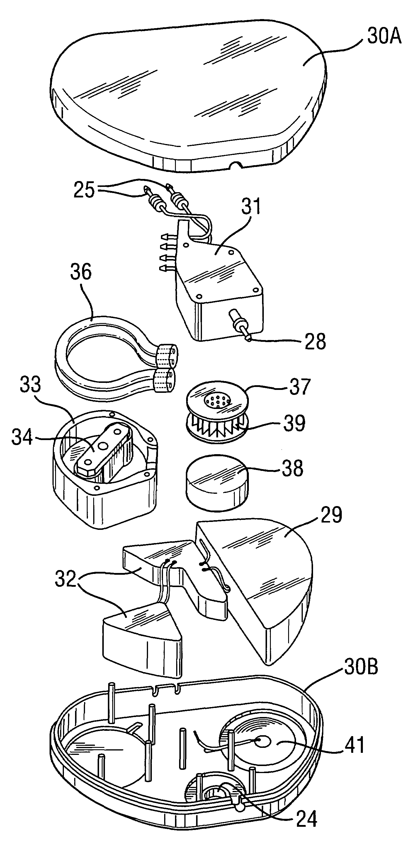
[0017]The invention allows a drug to be delivered to more than one site. This may be for the reasons outlined above that both sides of the brain need to be treated in conditions such as Parkinson's disease and Alzheimer's disease, or because multiple sites of delivery within a target volume may be necessary to optimize the distribution of the therapeutic agent. It is generally the rule that equal volumes of the therapeutic agent will need to be delivered to each site. The pump of the present invention achieves this with the advantage of being both compact and energy efficient.
[0022]It is also advantageous for the rotor to carry a roller for engagement with the length of tubing. Lower resistance and reduced wear result from the use of the roller.
[0027]By locating the pump unit and the drug reservoir separately, the pump unit will be more compact, and may allow a surgeon to implant it in a range of alternative locations where it is comfortable and access to the refill port is improved. Also, by locating the drug reservoir unit separately, the unit may be arranged to hold a greater volume of the drug, thereby reducing the number of clinic visits for percutaneous refilling, and also reducing the risk of introducing infection. A limitation on the size of the reservoir is the stability of the drug because there is no valve in the reservoir being of greater capacity than the total volume of a drug that will be delivered at the prescribed rate before the drug begins to degrade.
[0029]For drug delivery to the brain, it is preferable to position the pump close to the head. This minimizes the length over which the pump outflow tubing needs to be tunnelled subcutaneously, reduces the dead space in the tubing and also reduces the resistance to the flow of fluid, thereby improving energy efficiency for pump.
[0031]It is also preferred that the pump unit further includes a drug refill port through which the reservoir is filled. This is preferred because the pump unit may be unobtrusively implanted in the subclavicular region while the bulkier drug reservoir may be implanted in the abdominal wall. Whereas the anterior abdominal wall may contain considerable subcutaneous fatty tissue, the subclavicular region has comparatively little subcutaneous fat and so if the drug port is housed with the drug dispenser, it should be relatively easy to palpate percutaneously.

Problems solved by technology

The local delivery of drugs or therapeutic agents has particular application to the treatment of neurological conditions where the blood brain barrier prevents many systemically administered drugs from reaching the desired target, or where the delivery of drugs or therapeutic agents to targets other than the desired target may produce unacceptable side effects.
Passive drug dispensers are less reliable in delivering the desired dose than mechanical dispensers since the dose of drug delivered by passive dispenser depends upon the pressure in the drug filled reservoir, the resistance set by regulator, the resistance in the pump to catheter tubing, the resistance in the catheter, the pressure applied by the tissue (tissue turgor) at the catheter's delivery port, as well as the viscosity of the fluid being delivered.
With passive drug dispensers, the accuracy of drug delivery is least reliable when the flow rates are low and the regulator needs to impart a high resistance.
Proteins in suspension may also have a tendency to deposit within the fine tubing or etched channels of the passive regulator and further influence the flow rate.
This tends to make the pumps bulky for subcutaneous implantation because the reservoir alone may contain between 10 and 24 ml.
Nevertheless, when implanted in thin patients, the bulk of the pump can cause considerable inconvenience and discomfort.
If, on the other hand, the pump is deeply placed in the subcutaneous fat of an obese patient, finding the refill port can be also problematic.
Minimizing the volume of the reservoir of the pump has the disadvantage that the pump will require percutaneous refilling more frequently, thereby increasing the necessity for the patient to attend a clinic, and increasing the risk of introducing infection.
Delivering the drug to multiple sites by implanting multiple pumps of the types described in the prior art would be unacceptable, and only U.S. Pat. No. 5,752,930 discloses the delivery of a drug from a single pump to multiple sites.
Such a device will not facilitate drug infusion bilaterally into the brain or to other sites other than those along the axis of the implanted catheter.
Such an arrangement would not guarantee an even distribution of drug to each catheter because fluid will flow primarily down the catheter offering the least resistance.
This will put a great demand on the pump and will increase the stress on joints between the pump and the connector.

Method used


Image

  • Implantable drug delivery pump
  • Implantable drug delivery pump
  • Implantable drug delivery pump

Examples


Embodiment Construction

[0052]FIG. 4 is a schematic view showing an implantable drug delivery system. A reservoir unit 21 is shown implanted subcutaneously over the anterior abdominal wall of a patient, and preferably within the rectus sheath anterior to the rectus muscle. The reservoir unit 21 has the purpose of holding a volume of a drug for infusion, and since the unit 21 is quite bulky in order to retain as much drug as possible, such a location is very suitable. Leading from the reservoir unit 21 is a supply tube 22, which leads to a pump unit 23. The supply tube 22 is tunnelled subcutaneously between the reservoir unit 21 and the pump unit 23. The pump unit 23 is subcutaneously implanted in the subclavicular region. Implantation at this location is possible since the pump unit 23 is compact, made possible by the remote location of the reservoir unit 21. This location for the pump unit 23 is particularly advantageous since it should not prove to be inconvenient or uncomfortable to the patient, and yet...


PUM


Abstract

The pump includes a metering pump including a rotor, at least two lengths of tubing against which the rotor is movable to urge the drug therethrough, and an outlet port associated with each of the at least two lengths of tubing. In this way, a drug may be supplied to more than one neurological target.

Description

CROSS-REFERENCE TO RELATED APPLICATIONS[0001]This application claims priority to UK Serial No. 0209904.2, filed Apr. 30, 2002, which is incorporated herein by reference.BACKGROUND OF THE INVENTION[0002]1. Technical Field[0003]The present invention relates to an implantable drug delivery pump, a drug reservoir unit, and an implantable drug delivery system. Such pumps, units, or systems may be refilled with the drug, typically by percutaneous drug injections into reservoirs via body tissue.[0004]2. Background Art[0005]Implantable drug delivery systems may be used for systemic or local delivery of drugs. Examples of systemic drug delivery include the regulated infusion of insulin into the body tissues for the treatment of diabetes and the infusion of Apomorphine for the treatment of advanced Parkinson's disease. The local delivery of drugs or therapeutic agents has particular application to the treatment of neurological conditions where the blood brain barrier prevents many systemicall...

Claims


Application Information

Patent Timeline
Patent Type & Authority Patents(United States)
IPC IPC(8): A61M31/00A61K9/22A61M5/142
CPCA61M5/14232A61M5/14276A61M2209/045A61M2210/0693
Inventor GILL, STEVEN STREATFIELD
Owner RENISHAW PLC
Learn More