
Three-axis antenna scanning frame

A technology of three-axis antenna and scanning frame, which is applied in the direction of antenna, antenna radiation pattern, antenna support/installation device, etc., can solve the problems of low test efficiency and large error of measurement results, and achieve the effect of improving test efficiency and

Pending Publication Date: 2021-11-05
GUIZHOU AEROSPACE INST OF MEASURING & TESTING TECH
View PDF0 Cites 0 Cited by
  • Summary
  • Abstract
  • Description
  • Claims
  • Application Information

AI Technical Summary

Problems solved by technology

[0003] Based on the above, the present invention provides a three-axis antenna scanning frame to solve the problem of low test efficiency and large error in measurement results caused by multiple movements of the scanning frame, loading and unloading antennas, and moving positions when measuring space radiation signals in a specific area

Method used


Image

  • Three-axis antenna scanning frame
  • Three-axis antenna scanning frame
  • Three-axis antenna scanning frame

Examples


Embodiment Construction

[0039] In order to make the above objects, features and advantages of the present invention more comprehensible, specific implementations of the present invention will be described in detail below in conjunction with the accompanying drawings. In the following description, numerous specific details are set forth in order to provide a thorough understanding of the present invention. However, the present invention can be implemented in many other ways different from those described here, and those skilled in the art can make similar improvements without departing from the connotation of the present invention, so the present invention is not limited by the specific implementations disclosed below.

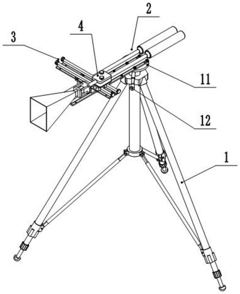
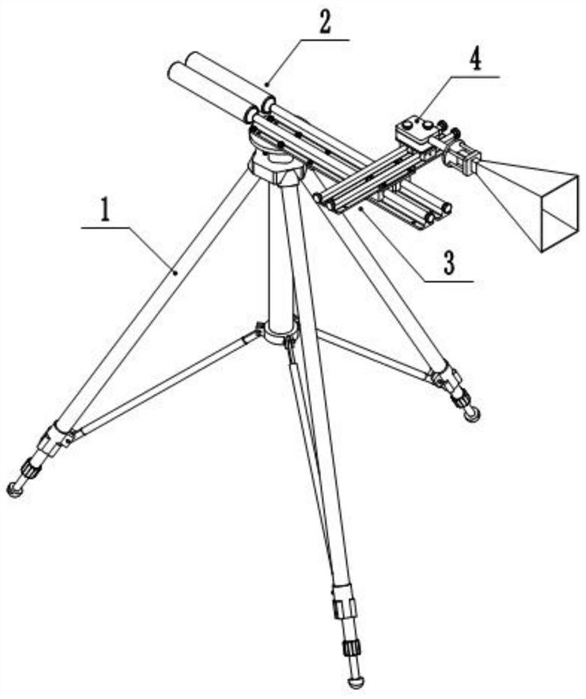
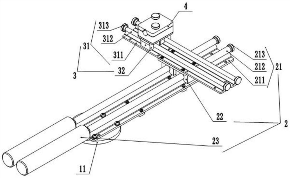
[0040] see Figure 1 to Figure 3 , a three-axis antenna scanning frame in this embodiment includes a tripod 1 , a horizontal adjustment mechanism 2 , a vertical adjustment mechanism 3 and an antenna fixing mechanism 4 . The tripod 1 plays a supporting role, and is mainly used to supp...


PUM


Abstract

The invention discloses a three-axis antenna scanning frame. The three-axis antenna scanning frame comprises a tripod; a transverse adjusting mechanism which comprises a transverse guide rail and a transverse adjusting seat, wherein the transverse guide rail is arranged on the tripod, and the transverse adjusting seat is slidably and adjustably arranged on the transverse guide rail; a longitudinal adjusting mechanism which comprises a longitudinal guide rail and a longitudinal adjusting seat, wherein the longitudinal guide rail is arranged on the transverse adjusting seat, the longitudinal adjusting seat is arranged on the longitudinal guide rail in a sliding adjusting manner, and the longitudinal guide rail is perpendicular to the transverse guide rail in direction; and an antenna fixing mechanism which is fixedly arranged on the longitudinal adjusting seat and is used for installing an antenna. Compared with the prior art, the repeated position switching and antenna installation and disassembly are avoided, the test efficiency and the reliability and stability of a measurement result are improved, and the problem that a whole space signal cannot be tested after one-time installation is effectively solved.

Description

technical field [0001] The invention relates to a three-axis antenna scanning frame, which belongs to the technical field of antenna supporting tools. Background technique [0002] Antenna scanning frames are often used when measuring space radiation signals in a specific area. However, at present, the antenna scanning frame is basically a fixed-point or one-way mobile device. If you want to test the space radiation signal, you need to change the antenna trajectory many times to achieve the purpose of measuring the radiation signal of a surface or a space. The method needs to move the scanning frame, loading and unloading the antenna multiple times, and move the position, the test efficiency is low, and the accuracy error becomes larger when the position is changed, so that the error of the measurement result increases accordingly. Contents of the invention [0003] Based on the above, the present invention provides a three-axis antenna scanning frame to solve the problem...

Claims


Application Information

Patent Timeline
IPC IPC(8): H01Q3/02H01Q1/12G01R29/10
CPCH01Q3/02H01Q1/12G01R29/10
Inventor 袁文石竹君林宏刘成
Owner GUIZHOU AEROSPACE INST OF MEASURING & TESTING TECH
Learn More