

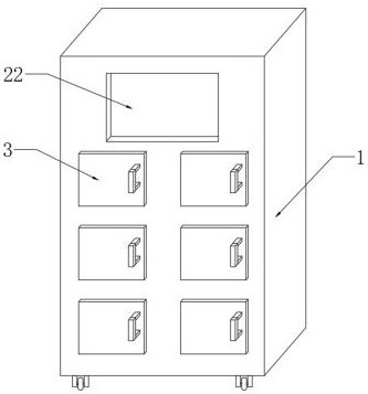
Battery replacement cabinet for charging storage battery
A battery and electric cabinet technology, applied in the field of power exchange cabinets, can solve problems such as device sliding, affecting user use, and battery sliding
- Summary
- Abstract
- Description
- Claims
- Application Information
AI Technical Summary
Problems solved by technology
Method used
Image

Examples
Embodiment 2
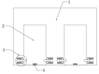
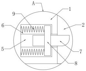
[0053]Embodiment 2. On the basis of Embodiment 1, the power group includes a motor 11, a fixed plate 12, a rotating shaft 13 and a gear 14. The number of fixed plates 12 is four, and the four fixed plates 12 are respectively fixedly connected in the fixed groove 10. At the top and bottom of the cavity, the motor 11 is fixed between the four fixed plates 12, the rotating shaft 13 is connected to the output end on one side of the motor 11, the gear 14 is fixedly sleeved on the circumferential surface of the rotating shaft 13, and the motor is started by electrical connection 11. The motor 11 will drive the rotating shaft 13 to rotate, and the rotating shaft 13 will drive the gear 14 on the circumferential surface to rotate. Since the tooth pattern on the surface of the skateboard 18 meshes with the tooth pattern on the circumferential surface of the gear 14, the gear 14 will drive the skateboard 18 slides downward, the slide plate 18 can support the whole device, thereby achievin...
Embodiment 3
[0054] Embodiment three, on the basis of embodiment one, the bottom of slide plate 18 is provided with base plate 19, and the bottom of base plate 19 is provided with anti-skid pad, and the quantity of base plate 19 is four, and the setting of four base plates 19 can make whole device It is more stable when fixing.
Embodiment 4
[0055] Embodiment 4, on the basis of Embodiment 1, a limiting groove 16 is provided on the other side of the chute 17, and the rotating shaft 13 is fixedly connected to a rotating block 15 at the end far away from the motor 11, and the rotating block 15 is rotatably inserted into the limiting groove 16, the setting of the rotating block 15 and the limiting groove 16 can make the rotating shaft 13 more stable when rotating.
PUM
 Abstract
Description
Claims
Application Information