Synchronous rapid replacement stainless steel container forming die

A molding die, stainless steel technology, applied in the field of stamping dies for stainless steel containers, can solve the problems affecting the bulging of stainless steel tubes, affecting the bulging speed of stainless steel round tubes, etc., to achieve the effect of convenient bulging and easy replacement

Pending Publication Date: 2021-11-16
浙江安胜科技股份有限公司
View PDF12 Cites 0 Cited by
  • Summary
  • Abstract
  • Description
  • Claims
  • Application Information

AI Technical Summary

Problems solved by technology

Due to the large number of vacuum cups, different types of vacuum cups need different molds to achieve bulging. When using hydraulic presses, frequent replacement of molds is required to meet the bulging of different types of stainless steel tubes, which affects the stainless steel tubes. Bulging, and due to the need to stop the machine to replace the mold, it affects the bulging speed of the stainless steel round tube

Method used


Image

  • Synchronous rapid replacement stainless steel container forming die
  • Synchronous rapid replacement stainless steel container forming die
  • Synchronous rapid replacement stainless steel container forming die

Examples


Embodiment 1

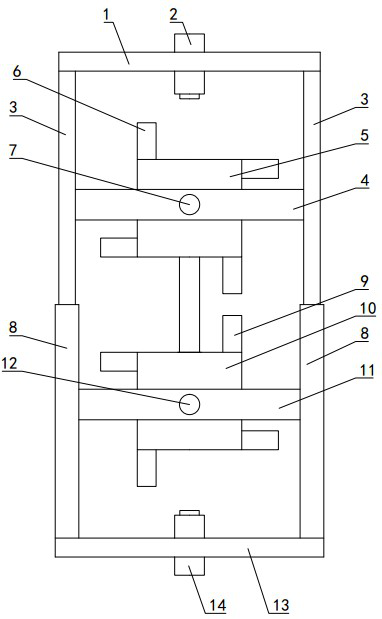
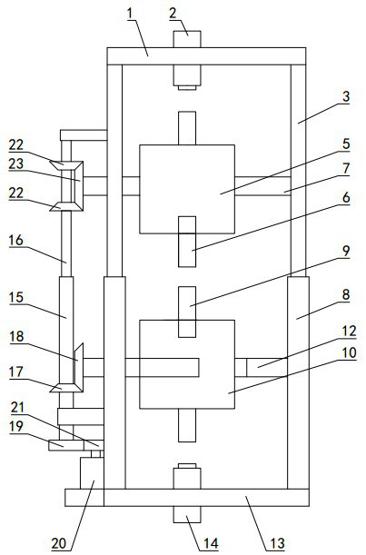
[0028] Such as Figure 1~2 Shown: This synchronous quick-change stainless steel container forming mold also includes an upper mounting frame 1, a lower mounting frame 13, a guide device, an upper mounting beam 4, and a lower mounting beam 11, and the upper mounting frame 1 and the lower mounting frame 13 are all horizontal Setting, the lower mounting frame 13 is arranged on the lower side of the upper mounting frame 1 at intervals, the upper rotating frame 5 and the lower rotating frame 10 are all arranged between the upper mounting frame 1 and the lower mounting frame 13, and the guide device is arranged on the upper mounting frame 1 and the lower mounting frame 13. Between the lower mounting frames 13, several guiding devices are evenly distributed around the upper rotating frame 5 and the lower rotating frame 10 at intervals. The upper mounting beam 4 is horizontally installed on the top of the guide device. The upper mounting beam 4 has two symmetrically arranged on both s...

Embodiment 2

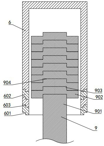
[0052] Such as Figure 6 As shown: the difference between embodiment 2 and embodiment 1 is that the upper mold cylinder 602 is spliced ​​by several arc-shaped plates, and the connecting groove of the upper mold body is set on the inner side of the bottom of the upper mold body, surrounding the top of the upper mold cylinder 602 A docking platform matched with the connection groove is provided, the docking platform extends into the connection groove, and the docking platform and the connection groove are attracted by magnets. A hoop 31 is arranged outside the upper mold barrel 602, so that the cooperation of each lower mold barrel 602 is reliable. During use, when a certain piece of the upper mold cylinder 602 is damaged or has a large amount of wear, only the corresponding piece of the upper mold cylinder 602 can be replaced.

[0053] The lower mold main body 902 has one and only one piece, and the lower mold main body 902 is spliced ​​by several pieces. The upper end of the ...


PUM


Abstract

The invention discloses a synchronous rapid replacement stainless steel container forming die, and belongs to the technical field of stainless steel container stamping dies. A plurality of upper dies (6) are installed on an upper rotating frame (5), and the upper dies (6) are arranged around a rotating shaft of the upper rotating frame (5) at intervals; a plurality of lower dies (9) are installed on a lower rotating frame (10), and the lower dies (9) are arranged around a rotating shaft of the lower rotating frame (10) at intervals; and a transmission mechanism is connected with the upper rotating frame (5) and the lower rotating frame (10) at the same time, so that the upper rotating frame (5) and the lower rotating frame (10) rotate synchronously. As the upper rotating frame and the lower rotating frame rotate synchronously, it is guaranteed that the paired upper dies and lower dies directly face each other to realize bulging of stainless steel round pipes; and it is only needed to enabling the upper rotating frame or the lower rotating frame to rotate during die replacement, so that die replacement is convenient and fast, and bulging of the stainless steel round pipes is facilitated.

Description

technical field [0001] The utility model relates to a synchronous fast changing stainless steel container molding die, which belongs to the technical field of stamping dies for stainless steel containers. Background technique [0002] During the production process of the stainless steel vacuum water cup, it is necessary to bulge the cut stainless steel round tube to make it reach the required size and shape. The bulge of the stainless steel round tube is usually carried out by stamping, through the upper mold and the lower The cooperation of the mold can realize the bulging of the stainless steel round tube. Due to the large number of vacuum cups, different types of vacuum cups need different molds to achieve bulging. When using hydraulic presses, frequent replacement of molds is required to meet the bulging of different types of stainless steel tubes, which affects the stainless steel tubes. Bulging, and due to the need to stop the machine to replace the mold, it affects t...

Claims


Application Information

Patent Timeline
Patent Type & Authority Applications(China)
IPC IPC(8): B21D37/10B21D37/14B21D51/18
CPCB21D37/10B21D37/14B21D51/18
Inventor 徐伟光刘成钢
Owner 浙江安胜科技股份有限公司
Why Eureka
Try Eureka