
A device and method for forming pipe fittings based on electromagnetic attraction

A technology of attractiveness and pipe fittings, which is applied in the field of forming and processing of metal pipe fittings, can solve problems such as limited application scenarios and difficulties in bulging and forming of small pipe fittings, and achieve the effects of reducing production costs, solving difficult problems, and improving utilization efficiency

Active Publication Date: 2019-06-25
CHINA THREE GORGES UNIV
View PDF5 Cites 0 Cited by
  • Summary
  • Abstract
  • Description
  • Claims
  • Application Information

AI Technical Summary

Problems solved by technology

However, the existing pipe fittings are still limited by the size of the blank and the coil, and the bulge forming of small pipes is difficult, which limits its application scenarios

Method used


Image

  • A device and method for forming pipe fittings based on electromagnetic attraction
  • A device and method for forming pipe fittings based on electromagnetic attraction
  • A device and method for forming pipe fittings based on electromagnetic attraction

Examples


Embodiment Construction

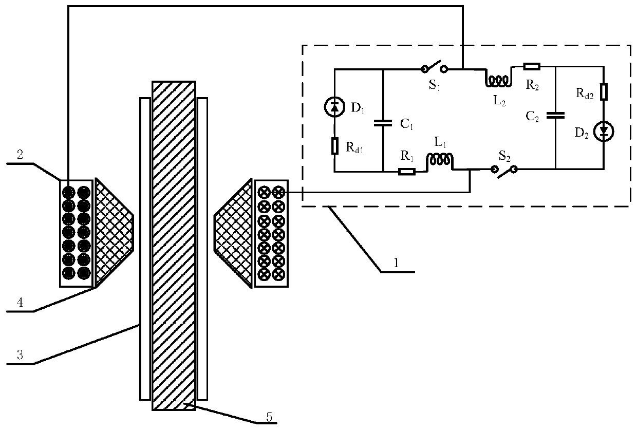
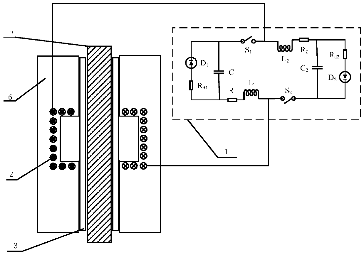
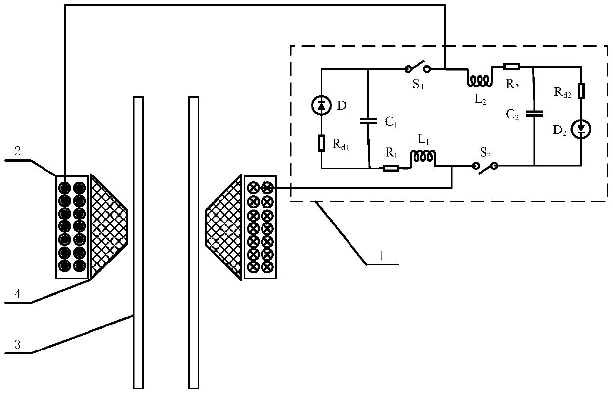
[0028] The present invention provides a tube forming device and method based on electromagnetic attraction. The specific technical solutions are as follows:

[0029] A pipe forming device based on electromagnetic attraction. The end of the metal pipe 3 is fixed by a mechanical structure or a hydraulic structure. A solenoid forming coil 2 is sleeved on the metal tube 3 to be formed, and fixed by a mechanical structure or a hydraulic structure to leave a certain forming gap.

[0030] The fixing method of mechanical structure or hydraulic structure is as follows:

[0031] A positioning ring is placed between the outer wall of the metal tube 3 and the inner wall of the solenoid forming coil 2 to make the two coaxial and to align the center area of ​​the solenoid forming coil 2 with the area to be formed of the metal tube wall 3. At the same time, a hydraulic press is used to restrain the entire device at the end to prevent the device from shaking in the axial direction.

[0032] A wide p...


PUM

PropertyMeasurementUnit
diameteraaaaaaaaaa

Abstract

The invention discloses a pipe fitting forming device and method based on electromagnetic attraction. The end of a metal pipe fitting is fixed; a solenoid forming coil is fixedly arranged at the outer part of a metal pipe fitting forming region in a sleeving manner; a forming gap is formed between the solenoid forming coil and the metal pipe fitting; and the solenoid forming coil is connected with a discharging circuit. The discharging circuit is used for applying wide width pulse current into the solenoid forming coil, and applying narrow width pulse current at a wide width pulse current peak, so that the synthesized current has a slow rising edge and an abrupt falling edge. At the rising edge of the synthesized current, the metal pipe fitting is stressed by repulsive force; at the falling edge of the synthesized current, the metal pipe fitting is stressed by attractive force; the attractive force is much larger than the repulsive force; the forming region of the metal pipe fitting moves towards the direction of the solenoid forming coil arranged at the outer part of the metal pipe fitting. Through the adoption of the pipe fitting forming device disclosed by the invention, a conventional manner of electromagnetic force manner can be changed, limitation in the prior art is overcome, and the application range of electromagnetic forming of pipe fittings is expanded, so that demands for different processing workpieces can be met.

Description

Technical field [0001] The invention belongs to the field of metal forming and manufacturing, and particularly relates to a tube forming device and method based on electromagnetic attraction, which is mainly used for forming and processing metal tubes. Background technique [0002] Electromagnetic forming is a high-energy, high-rate pulse forming technology. Compared with quasi-static forming, it has significant advantages such as fast forming speed, high forming quality, effective improvement of blank forming ability, clean and pollution-free. Therefore, it plays an important role in the lightweight process of aerospace, aviation, automobile and other manufacturing industries. Among them, lightweight alloys such as titanium alloys, aluminum alloys, and magnesium alloys are the preferred materials for lightweighting. However, these light alloys have poor forming plasticity at room temperature, and traditional forming methods are prone to wrinkles and springback; even limited by ...

Claims


Application Information

Patent Timeline
Patent Type & Authority Patents(China)
IPC IPC(8): B21D26/14
CPCB21D26/14
Inventor 熊奇唐红涛黄浩邱立江进波邓长征
Owner CHINA THREE GORGES UNIV
Learn More