Stress luminescence measurement device and stress luminescence measurement method
A technology of stress luminescence and measuring device, which is applied in measuring device, using optical device, and measuring force by measuring the change of optical properties of materials when they are stressed, and can solve problems such as sample breakage.
- Summary
- Abstract
- Description
- Claims
- Application Information
AI Technical Summary
Problems solved by technology
Method used
Image
Examples
Embodiment approach 1
[0025]
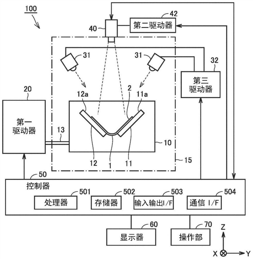
[0026] figure 1 It is a block diagram showing the overall configuration of the stress luminescence measurement device according to the first embodiment. The stress luminescence measurement device 100 according to Embodiment 1 is a device for measuring stress (strain) generated in a test object 1 (hereinafter also simply referred to as "sample") by using the luminescence phenomenon of a stress luminometer. The stress luminescence measurement device 100 can also be used to test durability against stress generated in the sample 1 .
[0027] Sample 1 is flexible, such as a flexible sheet or a flexible fiber. The flexible sheet can constitute a part of a flexible display of a communication terminal such as a smartphone or a tablet or a wearable device. Flexible fibers can form part of, for example, fiber optic cables.
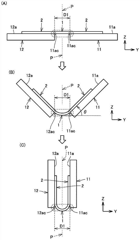
[0028] exist figure 1 In the example, Sample 1 is a flexible sheet of rectangular shape. A stress light emitter 2 is disposed on the surface of the ...
Embodiment approach 2
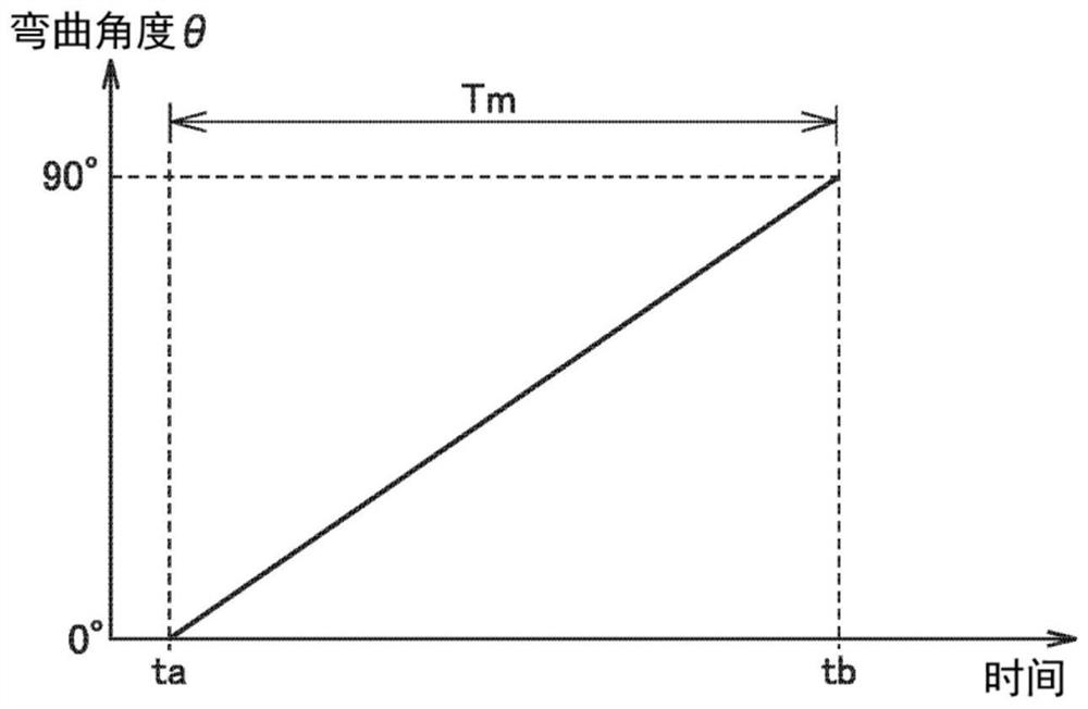
[0096] In Embodiment 1, based on a relational expression or table obtained in advance (refer to image 3 ) has been described as a configuration for calculating the bending angle θ of the sample 1 at the imaging timing, but it may also be a configuration for calculating the bending angle θ of the sample 1 from the captured image P1 obtained by the camera 40 .
[0097] In Embodiment 2, a method of calculating the bending angle θ of the sample 1 from the captured image P1 will be described. In addition, in Embodiment 2 and later, the structure of the stress luminescence measurement device 100 is the same as figure 1 The illustrated stress luminescence measurement device 100 has the same structure, so the description thereof will not be repeated. In addition, in addition to the step of obtaining the bending angle θ of sample 1 ( Figure 5 In addition to S40), the process of stress luminescence measurement is the same as Figure 5 The flowcharts shown are the same, and therefor...
Embodiment approach 3
[0110] In the stress luminescence measurement method according to Embodiment 3, the imaging timing of the camera 40 is set according to the bending angle θ of the sample 1 . Figure 10 It is a timing chart for explaining the operations of the light source 31 , the camera 40 , and the holder 10 in the stress luminescence measurement device 100 according to the third embodiment. exist Figure 10 In , waveforms showing timing of irradiation of excitation light from light source 31 , waveforms showing timing of imaging by camera 40 , and waveforms showing timing of operation of holder 10 by first driver 20 are shown.
[0111] Such as Figure 10 As shown, when imaging by the camera 40 starts at time t3, still images of the number corresponding to the frame rate of the camera 40 are generated. In Embodiment 3, the test is stopped for every frame, and the sample 1 is photographed by the camera 40 while maintaining the bending angle θ at the stop timing.
[0112] Specifically, by d...
PUM
 Abstract
Description
Claims
Application Information
 - R&D
- Intellectual Property
- Life Sciences
- Materials
- Tech Scout
- Unparalleled Data Quality
- Higher Quality Content
- 60% Fewer Hallucinations
Browse by: Latest US Patents, China's latest patents, Technical Efficacy Thesaurus, Application Domain, Technology Topic, Popular Technical Reports.
© 2025 PatSnap. All rights reserved.Legal|Privacy policy|Modern Slavery Act Transparency Statement|Sitemap|About US| Contact US: help@patsnap.com


