Microswitch assembling equipment

A technology for micro-switches and assembling equipment, applied in electrical switches, assembling machines, metal processing equipment, etc., can solve the problems of reduced production efficiency, long time consumption, dislocation of moving pieces, etc., and achieves the effect of reasonable structural design

Pending Publication Date: 2021-11-26
HUIZHOU QINHAN TECH
View PDF0 Cites 0 Cited by
  • Summary
  • Abstract
  • Description
  • Claims
  • Application Information

AI Technical Summary

Problems solved by technology

[0005] From the above, it can be known that in the prior art, the micro switch is usually assembled manually with the jig (4), but the prior art has the following problems: since the micro switch involves many assembly parts and the assembly parts Relatively small, it is very difficult to assemble the micro switch manually with the jig (4), so it takes too long, which greatly reduces the production efficiency of using the jig (4) to assemble the micro switch
In the process of using the jig (4) to assemble the micro switch, press the left end of the moving piece (19) down into the slot (1704) of the left bracket (1703) of the base (17), and simultaneously make the moving piece (19) It is the most difficult step to realize that the right end of the piece (19) moves to the right between the bracket (18) and the block (1702) of the base (17), because in the process of pressing down the left end of the moving piece (19) In the middle, due to the action of the tension force, the spring (20) will change from a relatively relaxed state to a relatively tense state. During this transformation process, due to the lack of binding force, the spring (20), the moving piece (19) It is very easy to cause movement dislocation, which increases the difficulty of assembling the micro switch

Method used


Image

  • Microswitch assembling equipment
  • Microswitch assembling equipment
  • Microswitch assembling equipment

Examples


Embodiment Construction

[0032] The following will clearly and completely describe the technical solutions in the embodiments of the present invention in conjunction with the accompanying drawings in the embodiments of the present invention, but this does not constitute a limitation to the protection scope of the present invention.

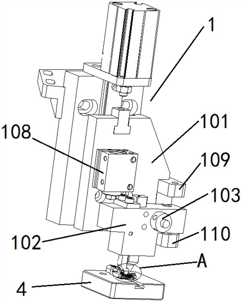
[0033] In the present invention, for a clearer description, the following description is made: the observer faces the attached figure 1 For observation, the left side of the observer is set as left, the right side of the observer is set as right, the front of the observer is set as front, the back of the observer is set as back, the top of the observer is set as up, and the bottom of the observer is set as bottom. It should be pointed out in the text The terms "front end", "rear end", "left side", "right side", "middle", "above", "below", etc. indicating the orientation or positional relationship are based on the orientation or positional relationship set in the drawings ...


PUM


Abstract

The invention discloses microswitch assembling equipment. The microswitch assembling equipment comprises a moving plate downward pressing device, the moving plate downward pressing device comprises a first mounting plate and a downward pressing module, the first mounting plate is provided with a first rotating shaft extending in the horizontal direction, and the first mounting plate is rotatably connected with the middle part of the downward pressing module through the first rotating shaft; and a first pressing plate, a second pressing plate and a positioning rod are arranged at the bottom end of the downward pressing module, the first pressing plate and the second pressing plate are sequentially distributed in the extending direction of the first rotating shaft, a U-shaped groove is formed between the first pressing plate and the second pressing plate, and the positioning rod is located on one side outside the U-shaped groove. The microswitch assembling equipment is reasonable in structural design and can be matched with a clamp to assemble a microswitch, manual participation is not needed, and therefore the assembling efficiency of the microswitch is greatly improved.

Description

technical field [0001] The invention relates to the field of micro switch assembly technology, in particular to micro switch assembly equipment. Background technique [0002] The micro switch is a contact mechanism with a small contact interval and a quick action mechanism, which performs a switching action with a specified stroke and a specified force. It is covered with a casing and has a drive rod on the outside. Small, hence the name micro switch, also called sensitive switch. [0003] see figure 2 , Figure 12 , Figure 13 , the micro switch is usually composed of a base (17), a bracket (18), a moving piece (19), and a spring (20), wherein the right end of the bracket (18) is engaged with the right card seat (1701) of the base (17) Cooperate, the right end of the moving piece (19) and the block (1702) of the base (17) carry out the upper and lower limit cooperation, the left end of the moving piece (19) and the draw-in groove (1704) of the left card seat (1703) of t...

Claims


Application Information

Patent Timeline
Patent Type & Authority Applications(China)
IPC IPC(8): B23P21/00H01H11/00
CPCB23P21/006H01H11/00
Inventor 刘永林马建和巩建涛刘志琦温福钊
Owner HUIZHOU QINHAN TECH
Why Eureka
Try Eureka