Power cable erection conveying device having clamping mechanism

A technology of power cables and transmission devices, which is applied in the direction of overhead lines/cable equipment, etc., can solve the problems of inability to fix cables and inconvenient adjustment of cable heights, and achieve the effect of improving performance

Inactive Publication Date: 2019-09-20
蚌埠珠领智能科技有限公司
View PDF7 Cites 3 Cited by
  • Summary
  • Abstract
  • Description
  • Claims
  • Application Information

AI Technical Summary

Problems solved by technology

[0006] In order to solve the above technical problems, the present invention provides a power cable erecting and conveying device with a clamping mechanism to solve the problem that only one group of cables can be erected in the above background technology. The height adjustment of the cable is inconvenient, and the cable cannot be fixed at the same time

Method used


Image

  • Power cable erection conveying device having clamping mechanism
  • Power cable erection conveying device having clamping mechanism
  • Power cable erection conveying device having clamping mechanism

Examples


Embodiment

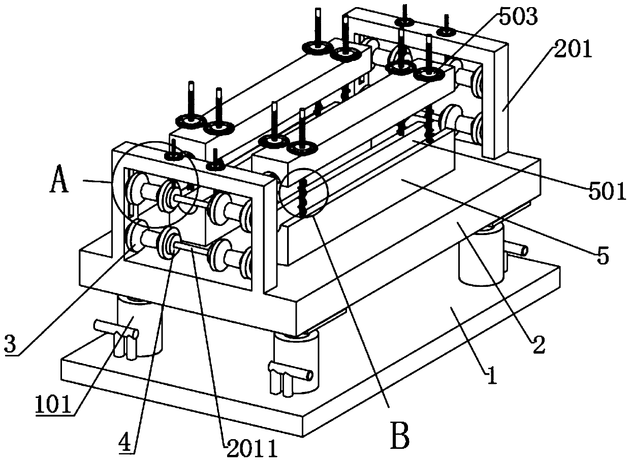
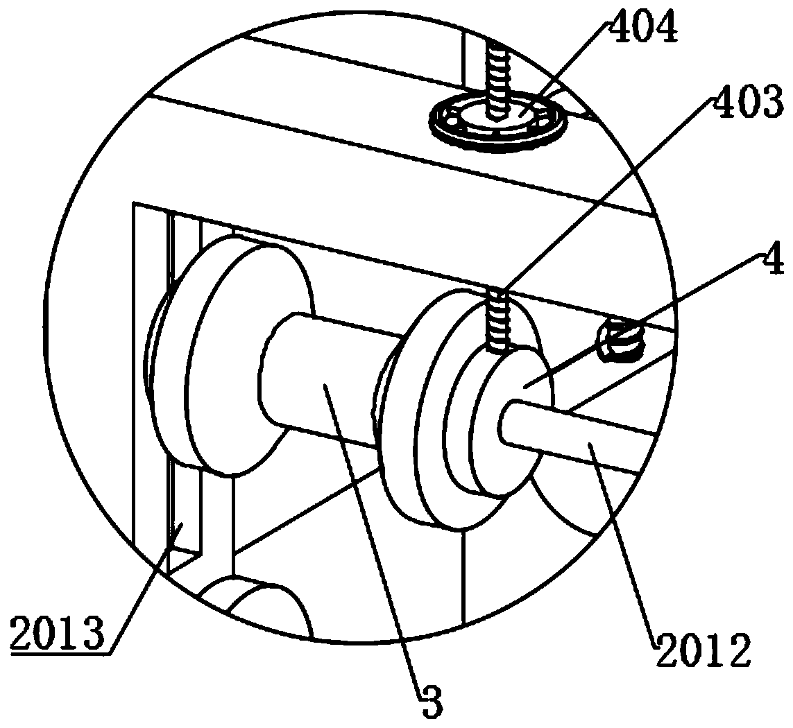
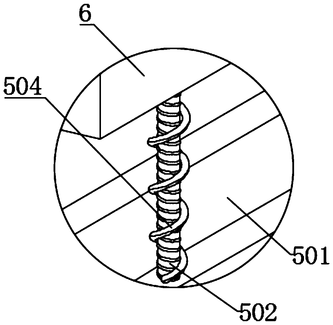
[0033] as attached figure 1 To attach Figure 7 Shown:

[0034] The present invention provides a power cable erecting and conveying device with a clamping mechanism, including a bottom plate 1, a jack 101, an adjusting support plate 2, a square frame 201, a fixing cross bar 2011, an adjusting cross bar 2012, an adjusting chute 2013, and a pulley 3 , through hole 301, bearing 302, limiting circular plate 4, internal thread hole 401, ball 402, adjusting screw A403, adjusting hand wheel A404, lower bar 5, arc groove 501, adjusting screw B502, adjusting hand wheel B503 , spring 504 and upper strip 6; jacks 101 are fixedly installed on the top four ends of the bottom plate 1, and the top of the jack 101 is screwed into the bottom end surface of the adjustment brace 2 by screws, and the adjustment brace 2 Both ends are provided with a square frame 201, and the inner lower end of the square frame 201 is welded with a fixed cross bar 2011, and both ends of the fixed cross bar 2011 a...


PUM


Abstract

The invention provides a power cable erection conveying device having a clamping mechanism. The power cable erection conveying device comprises jacks, pulleys, limit circular plates, lower bar plates, arc grooves and springs. The top portions of the jacks are screwed into the bottom end surface of an adjustment support plate through screws; the two ends of each fixation cross bar are sleeved by pulleys with grooves in the middle; the fixation cross bars at the two sides of the pulley are provided with the limit circular plates; each adjustment cross bar is adjusted to be inserted into and make contact with the inner wall of a corresponding sliding groove; two groups of lower bar plates are welded in the middle portion of the adjustment support plate; the top middle portion of each lower bar plate is provided with the arc groove; the two ends of each arc groove are respectively welded by an adjusting screw rod B; and each adjusting screw rod B is sleeved by the spring. The height of the adjustment support plate is adjusted through jacks to make the placed height of cables on the pulley match with the erection height; the two cables are placed between the upper and lower opposite pulleys; the two groups of cables can be erected simultaneously; and adjustment hand wheels B can be rotated to make upper bar plates to move downward so as to clamp the cables.

Description

technical field [0001] The invention belongs to the technical field of power cable laying, and more specifically relates to a power cable erecting and conveying device with a clamping mechanism. Background technique [0002] Wire and cable are known as the "nerves" and "vessels" of modern cities. This industry shoulders the supporting functions of the national economy pillars in various industries, such as electric power, communications, railways, rails, urban transportation, ships, automobiles, petrochemicals, The demand for wires and cables in industries such as construction, highways, and home appliances is increasing, and the installation of wires is difficult and expensive, especially in mountainous areas. cost and reduce difficulty. It is also becoming more and more important. [0003] The inventor found similar patents in the process of searching for patents. For example, in the patent with the application number: CN201520779947.7, a power cable erecting and conveyi...

Claims


Application Information

Patent Timeline
IPC IPC(8): H02G1/02
CPCH02G1/02
Inventor 娄中凯凌红旭
Owner 蚌埠珠领智能科技有限公司
Why Eureka
Try Eureka