Stabilizing bicycle seat

a bicycle seat and stabilizer technology, applied in the field of bicycle seats, can solve the problems of cycling often shifting lateral positions on the seat undesired, no solutions exist to reduce energy waste, etc., and achieve the effects of stable body-to-seat interface, simple installation, and increased power

Inactive Publication Date: 2015-02-05
WONG JON +1
View PDF0 Cites 17 Cited by
  • Summary
  • Abstract
  • Description
  • Claims
  • Application Information

AI Technical Summary

Benefits of technology

[0019]In a ninth embodiment of the bicycle seat system, the longitudinal groove of the seat includes an upwardly-projecting longitudinal catch that has both a forward undercut and a rearward undercut. The posterior seat engagement portion of the lower garment projects downwardly and includes a groove therein that is adapted for engaging the longitudinal catch of the seat. The groove includes a forward undercut and a rearward undercut, each that cooperative with the forward and rearward undercuts, respectively, of the longitudinal catch to prevent upward movement of the person off of the seat when so engaged.
[0020]The present invention is a bicycle seat attachment, replacement bicycle seat, or bicycle seat system that provides for inhibiting unwanted forward and rearward sliding of the cyclist on the seat, unwanted lateral movement of the cyclist on the seat, or a combination thereof. The present system allows the cyclist to generate more power to the pedals through a more stable body-to-seat interface. The present invention is relatively simple to install either on a new or used bicycle, and is intuitive to use. Further, the present invention is relatively inexpensive to manufacture and lightweight. Other features and advantages of the present invention will become apparent from the following more detailed description, taken in conjunction with the accompanying drawings, which illustrate, by way of example, the principles of the invention.

Problems solved by technology

However, heretofore no solutions exist for decreasing energy wasted by a cyclist trying to maintain a desired position on the bicycle's seat.
Likewise, around turns a cyclist frequently finds himself shifting lateral position on the seat undesirably.
Further, such a needed device would be relatively inexpensive to manufacture and lightweight.

Method used


Image

  • Stabilizing bicycle seat
  • Stabilizing bicycle seat
  • Stabilizing bicycle seat

Examples


second embodiment

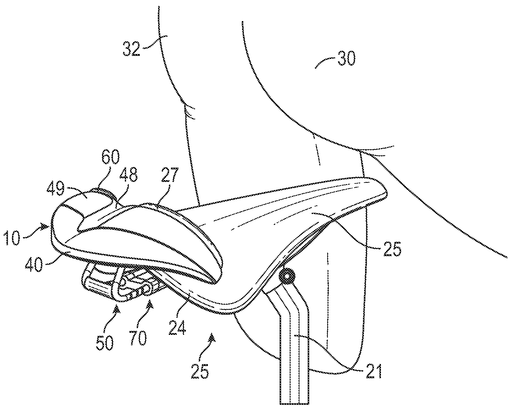
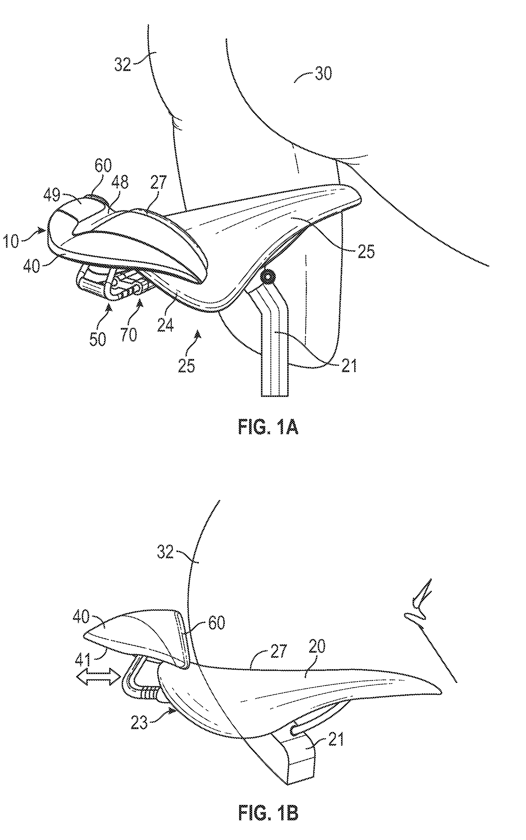
[0039]FIGS. 2A and 2B illustrate a second embodiment wherein the bicycle seat attachment 10 includes the base 40, a forward end 48, a rearward end 42, and a downwardly-projecting rigid loop 80 adapted to receive therein a forward thin portion 26 of the bicycle seat 20. The rearward end 42 terminates in an upwardly-raised flange 90 adapted to buttress the posterior 32 of the person 30. The forward end 42 terminates in a resilient upwardly-projecting tongue 100. The base 40 thereby forms a saddle 110 for inhibiting forward and rearward motion in the seat 20 by the person 30. Preferably the upwardly-projecting tongue 100 is malleable and, as such, selectively angularly adjustable. Further, preferably the upper side 49 of the base 40 includes a plurality of laterally traversing ridges 130 for inhibiting through friction backward and forward movement of the person 30 while seated thereon.

[0040]In such an embodiment, the clamping mechanism 50 is fixed to the rearward end 42 of the base 40...

seventh embodiment

[0048]In a seventh embodiment, illustrated in FIG. 7, the top side 118 of the bicycle seat 11 includes the longitudinal groove 160 and the lower garment includes a downwardly-projecting fin 270 from the posterior seat engagement portion 210. The fin 270 may be curved from front to back, whereby when engaged with the longitudinal groove 160 the person 30 may adjust his angular position from forward to rearward in the seat 11 while still being inhibited from lateral motion from side to side. As such, when the person 30 is seated on the seat 11 while wearing the lower garment 200, the fin 270 of the garment 200 engages the longitudinal groove 160 of the seat 20 to inhibit lateral motion of the person 30 while seated. In one embodiment, the fin 270 is selectively detachable from the lower garment 200, such as with a tongue-in-groove arrangement (not shown), or snap-in friction fit connection (not shown), or the like.

[0049]In such an embodiment, the top side 118 of the seat 11 may furthe...

eighth embodiment

[0050]In the invention, illustrated in FIG. 8, the posterior seat engagement portion 210 of the lower garment 200 includes a downwardly-projecting platform 280 adapted for engagement with the longitudinal groove 160 of the seat 11. A bottom side 162 of the longitudinal groove 160 may further include the plurality of laterally-traversing ridges 130, and the platform 280 of the lower garment 200 may further include the plurality of grooves 220 each adapted to receive one of the laterally traversing ridges 130 of the longitudinal groove 160. As such, when the person 30 is seated on the seat 11 while wearing the lower garment 200, the upwardly-extending ridges 130 of longitudinal groove 160 engage the grooves 220 of the platform 280 to inhibit forward and backward motion of the person 30 while seated. When the person 30 elevates his posterior 32 slightly off of the seat 11, he is free to adjust his position forward or backward with respect to the seat11 before sitting again on the seat ...


PUM


Abstract

A cyclist's desired position on a bicycle seat is maintained by a bicycle seat attachment, a replacement seat for either a new or used bicycle, or a bicycle seat system comprising a seat configured to cooperate in a variety of ways with a lower garment worn by the cyclist. The cyclist may be inhibited from moving forward or backward, left or right, or even up and down by a plurality of cooperative grooves, ridges, fins and catches in the seat or in conjunction with the seat and the lower garment.

Description

CROSS-REFERENCE TO RELATED APPLICATIONS[0001]This application claims the benefit of U.S. Provisional Patent Application 61 / 860,187, filed on Jul. 30, 2013, and incorporated herein by reference.STATEMENT REGARDING FEDERALLY SPONSORED RESEARCH AND DEVELOPMENT[0002]Not Applicable.FIELD OF THE INVENTION[0003]This invention relates to bicycle seats, and more particularly to a stabilizing bicycle seat that provides increased power transfer from the cyclist to the bicycle.DISCUSSION OF RELATED ART[0004]Serious bicycle athletes are concerned about using energy efficiently. For example, pedals with shoe clips allow the cyclist to add power on the upswing of the pedals to provide even more power and speed. Aerodynamic helmets and other accessories are common to reduce drag. However, heretofore no solutions exist for decreasing energy wasted by a cyclist trying to maintain a desired position on the bicycle's seat.[0005]Frequently a cyclist will find himself having slid back on the seat and the...

Claims


Application Information

Patent Timeline
Patent Type & Authority Applications(United States)
IPC IPC(8): B62J1/28A41D13/00B62J1/00
CPCB62J1/28A41D13/0015B62J1/007A41D1/084A41D2400/80
Inventor WONG, JONPETERSON, TOM
Owner WONG JON
Why Eureka
Try Eureka