Loop heat pipe

A heat pipe and loop technology, applied in the field of loop heat pipes, can solve problems such as difficult heat dissipation and increased heat generation of heating components

Pending Publication Date: 2021-11-30
SHINKO ELECTRIC IND CO LTD
View PDF0 Cites 0 Cited by
  • Summary
  • Abstract
  • Description
  • Claims
  • Application Information

AI Technical Summary

Problems solved by technology

[0009] In recent years, with the increase in signal processing speed, the heat generation in heat-generating components has increased, making it difficult to dissipate heat sufficiently in the prior art loop-type heat pipes

Method used


Image

  • Loop heat pipe
  • Loop heat pipe
  • Loop heat pipe

Examples


no. 1 example

[0033] [Structure of the loop heat pipe of the first embodiment]

[0034] First, the structure of the loop heat pipe according to the first embodiment will be described. figure 1 is a schematic plan view illustrating the loop-type heat pipe according to the first embodiment.

[0035] refer to figure 1 , the loop heat pipe 1 includes: an evaporator 10, a first condenser 21, a second condenser 22, a first vapor pipe 31, a second vapor pipe 32, a first liquid pipe 41, a second liquid pipe 42 and a connecting portion 43. The loop heat pipe 1 can be accommodated, for example, in portable electronic devices 2 such as smartphones and tablet terminals.

[0036] In the loop heat pipe 1 , the evaporator 10 has a function of evaporating the working fluid C to generate the vapor Cv. Both the first condenser 21 and the second condenser 22 have a function of condensing the vapor Cv of the working fluid C. The first liquid pipe 41 is connected to the first condenser 21 . The second liq...

no. 2 example

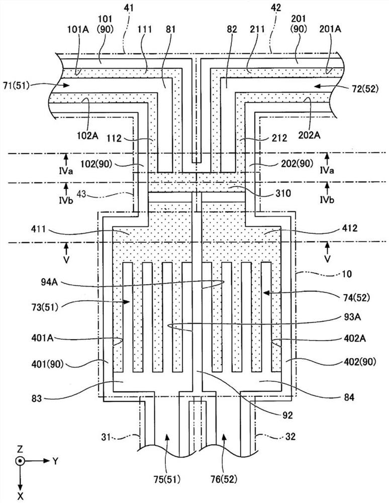
[0064] In the second embodiment, the configuration of the evaporator 10 is different from that of the first embodiment. In the second embodiment, descriptions of the same constituent parts as those of the above-described embodiments may be omitted. Figure 6 is a schematic plan view depicting the evaporator 10 , the first liquid pipe 41 , the second liquid pipe 42 , the connecting portion 43 , the first vapor pipe 31 , and the second vapor pipe 32 of the loop heat pipe according to the second embodiment. exist Figure 6 , not shown as the outermost metal layer on one side ( Figure 4A , Figure 4B and Figure 5 Metal layer 61) shown in .

[0065] In the second embodiment, the second condenser 22 is arranged in an environment that is easier to dissipate heat than the first condenser 21 . For example, the second condenser 22 is arranged in a larger area than the first condenser 21 , or a cooling fan is arranged in the vicinity of the second condenser 22 . The cross-section...


PUM


Abstract

The invention provides a loop heat pipe. The loop heat pipe includes: an evaporator; a first condenser; a second condenser; a first liquid pipe having a first flow path and configured to connect the evaporator and the first condenser; a second liquid pipe having a second flow path and configured to connect the evaporator and the second condenser; a first vapor tube configured to connect the evaporator and the first condenser; a second vapor pipe configured to connect the evaporator and the second condenser; and a connection part having a first porous body and configured to connect the first liquid tube and the second liquid tube to the evaporator. The evaporator has a third flow path connected to the first liquid tube and the first vapor tube, a fourth flow path connected to the second liquid tube and the second vapor tube, and a partition wall configured to partition the third flow path and the fourth flow path.

Description

technical field [0001] The invention relates to a loop heat pipe. Background technique [0002] In the prior art, a heat pipe is known as a device configured to cool a heat-generating component such as a CPU (Central Processing Unit) mounted on an electronic device. A heat pipe is a device configured to transfer heat by using a phase change of a working fluid. [0003] As the heat pipe, there can be exemplified a loop-type heat pipe including: an evaporator configured to evaporate a working fluid by the heat of a heat-generating component; and a condenser configured to cool and condense the evaporated working fluid, Wherein the evaporator and the condenser are connected to each other by a liquid pipe and a vapor pipe forming a loop-shaped flow path. In a loop-type heat pipe, a working fluid flows in one direction in a loop-shaped flow path. [0004] Both the evaporator and the liquid pipe of the loop heat pipe are provided with porous (porous) bodies, so that the working ...

Claims


Application Information

Patent Timeline
Patent Type & Authority Applications(China)
IPC IPC(8): F28D15/02F28D15/04G06F1/20
CPCF28D15/0266F28D15/04G06F1/20F28D15/0275F28D15/043F28D15/046
Inventor 町田洋弘
Owner SHINKO ELECTRIC IND CO LTD
Why Eureka
Try Eureka