Eureka AIR delivers breakthrough ideas for toughest innovation challenges, trusted by R&D personnel around the world.

Simple hydraulic valve

A hydraulic valve, a simple technology, applied in the field of hydraulic valves, can solve the problems of poor sealing effect at the joint, fixed in a proper position, unable to replace different fixed blocks, etc., to achieve enhanced sealing effect, enhanced sealing, and enhanced sealing sexual effect

Pending Publication Date: 2021-12-10
扬州旭欣气动液压设备有限公司
View PDF7 Cites 1 Cited by
  • Summary
  • Abstract
  • Description
  • Claims
  • Application Information

AI Technical Summary

Problems solved by technology

[0005] In order to solve the above technical problems, the present invention provides a simple hydraulic valve to solve the problem that when the existing hydraulic valve is in use, the sealing effect of the connection is poor, and the sealing cannot be automatically strengthened by force, and the existing hydraulic valve is in use. When in use, it cannot be spliced ​​and fixed conveniently, and different fixing blocks cannot be replaced and fixed in place

Method used


Image

  • Simple hydraulic valve
  • Simple hydraulic valve
  • Simple hydraulic valve

Examples


Embodiment

[0034] as attached figure 1 to attach Figure 8 Shown:

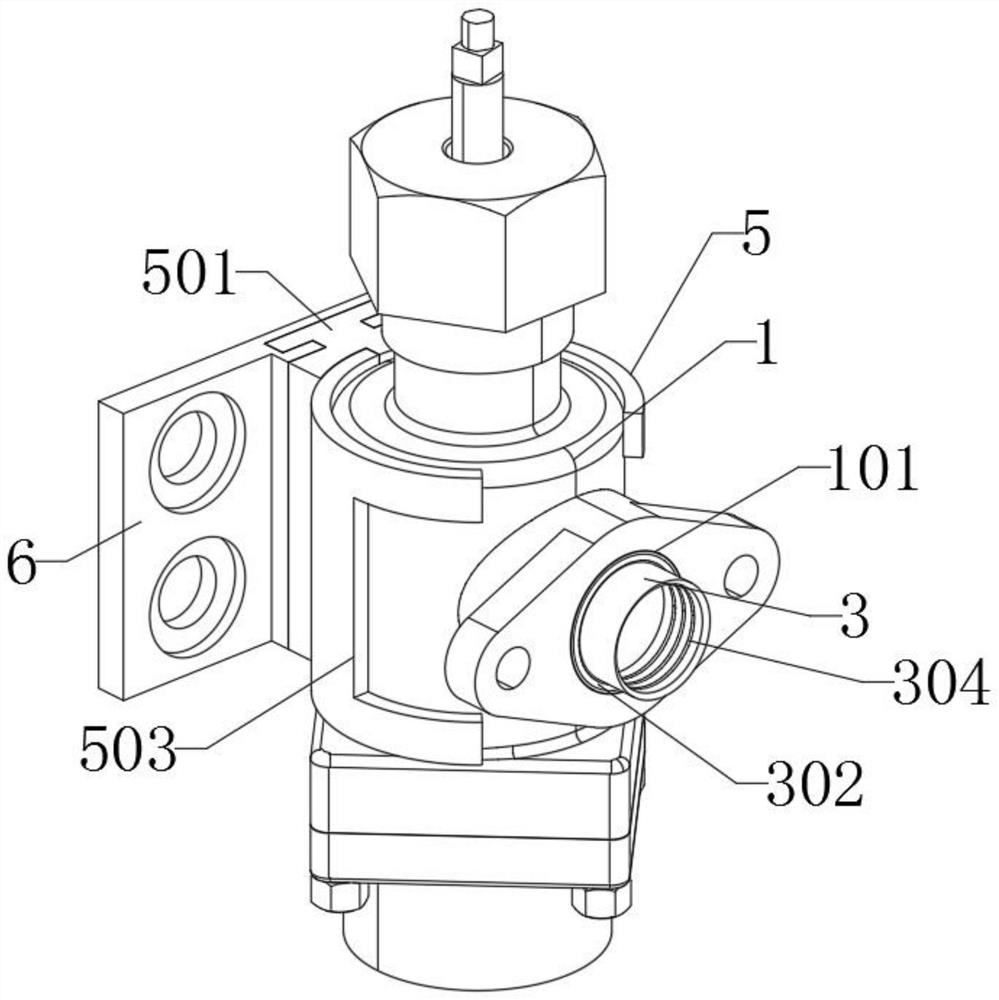
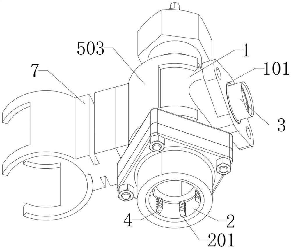
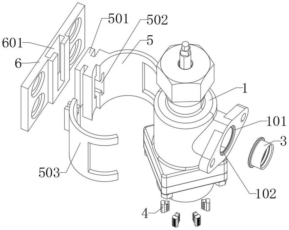
[0035] The present invention provides a simple hydraulic valve, which includes a main body 1, a bottom hole 2, a sealing member 3, a fixing member 4, a fixing ring 5, a fixing plate 6 and a joint member 7; the main body 1 is a hydraulic valve body, and the side of the main body 1 The side is provided with a connecting end; the bottom hole 2 is arranged at the bottom of the main body 1; the fixing piece 4 is installed inside the bottom hole 2, and the outer end of the fixing piece 4 is embedded in the inside of the installation hole 201, and the fixing piece 4 is arranged in a ring shape; The fixing plate 6 is on the outside of the main body 1, and the slot 601 of the fixing plate 6 is inserted with a connector 501; Connector 501 is installed inside 702;

[0036]The seal 3 includes an inner hole 301, a convex strip 302, an inner groove 303, and a stress groove 304. The seal 3 is a cylindrical tubular structure with a p...


PUM


Abstract

The invention provides a simple hydraulic valve, relates to the technical field of hydraulic valves, and aims to solve the problems that when a conventional hydraulic valve is used, the sealing effect at the connecting position is poor, and automatic stress cannot be carried out to enhance sealing. The simple hydraulic valve comprises a main body, a bottom hole and a sealing piece, the main body is a hydraulic valve body, a connecting end is arranged on a side edge of the main body, the bottom hole is formed in the bottom of the main body. The sealing piece is used for being installed in a connecting hole of the main body so that when the connecting end of the main body is connected, the sealing piece can be embedded and installed in the connecting hole, when a pipeline is connected, the outer end of the sealing piece can be inserted into the pipeline, and when the main body is used and liquid passes through, the sealing piece can make contact with the interior of a stress groove so that the stress groove can be automatically stressed, outward expansion is enhanced, the sealing piece is better attached to the interior of the pipeline, and the sealing effect is enhanced.

Description

technical field [0001] The invention belongs to the technical field of hydraulic valves, and more specifically relates to simple hydraulic valves. Background technique [0002] The hydraulic valve is an automatic component operated by pressure oil. It is controlled by the pressure oil of the pressure distribution valve. It is usually used in combination with an electromagnetic pressure distribution valve. It can be used to remotely control the on-off of oil, gas, and water pipeline systems in hydropower stations. Clamping, control, lubrication and other oil circuits. There are direct-acting and pilot-operated types, and the pilot-operated type is mostly used. [0003] For example, the application number: CN111173796A relates to a hydraulic valve, which includes an upper valve body, a lower valve body, a pressure compensation plate and a valve core. The upper surface of the lower valve body is respectively provided with a lower oil inlet groove, a lower oil outlet groove and...

Claims


Application Information

Patent Timeline
Patent Type & Authority Applications(China)
IPC IPC(8): F15B13/02F16L21/02F16L51/00
CPCF15B13/021F16L21/022F16L51/00
Inventor 张卫建
Owner 扬州旭欣气动液压设备有限公司
Why Eureka
Eureka Blog
Learn More