Encapsulation and transfer mechanism for coal samples
A technology for coal samples and sample bottles, which is applied to packaging, closures, conveyors, etc., can solve the problems of poor packaging accuracy of coal sample bottles, inability to automatically process coal slag, and affect normal packaging of bottle caps, etc., to solve coal slag processing and improve The effect of sealing the equipment and ensuring the accuracy of the sealing
- Summary
- Abstract
- Description
- Claims
- Application Information
AI Technical Summary
Problems solved by technology
Method used
Image

Examples
Embodiment 1
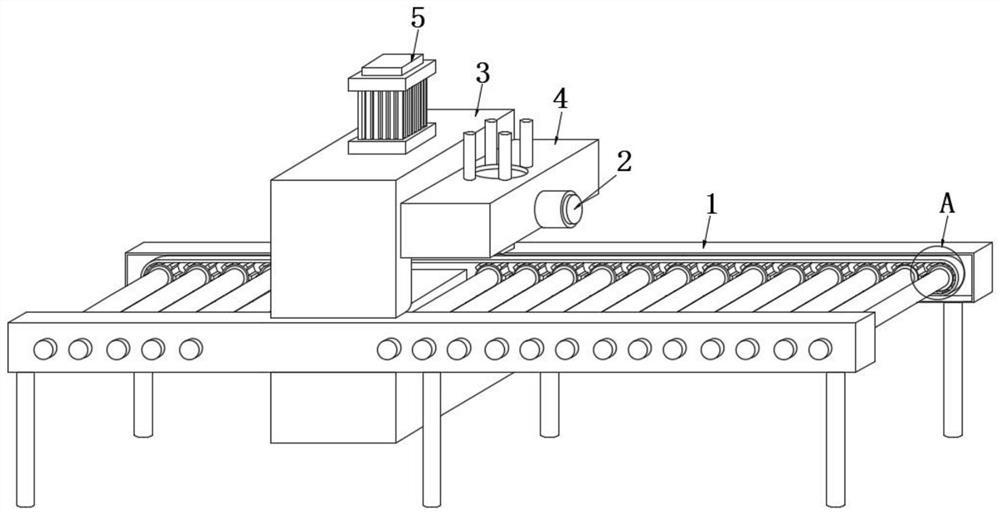
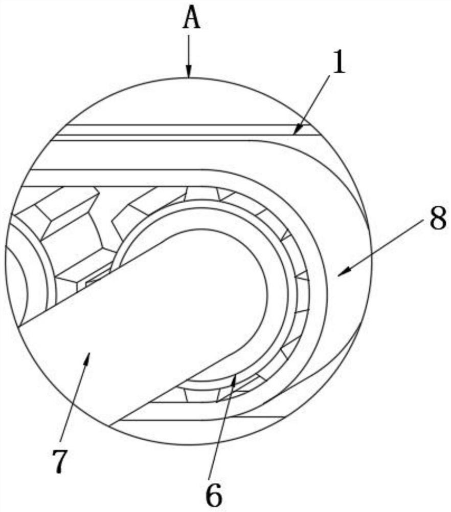
[0037] see Figure 1-5 As shown, the present invention is a packaging and transporting mechanism for coal samples, including a support frame 1, a straightening mechanism 10 and a blowing mechanism 11, the inner part of the support frame 1 is rotatably connected to a transmission gear 6, and the two transmission gears 6 are fixedly connected to the conveying roller 7, The outer casing of the transmission gear 6 is connected to the conveyor belt 8, the upper surface of the support frame 1 is fixedly connected to the protective frame 3, and one side of the protective frame 3 is fixedly connected to the bottle cap stack 4. By controlling the air valve 2 on the side of the bottle cap stack 4, the bottle The cap stack 4 pushes the bottle cap to the bottom of the screw cap plate 14. When the bottle cap moves to the stabilizer splint 154, it squeezes the stabilizer splint 154 on both sides first, and the limit spring 153 on the left side of the stabilizer splint 154 is in the hollow tu...
Embodiment 2
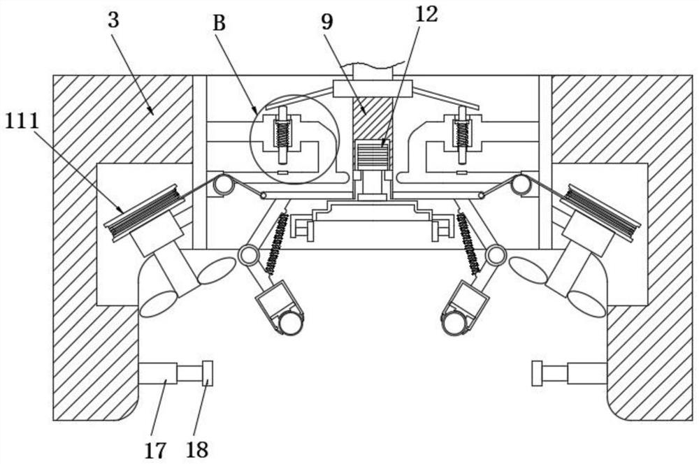
[0040] like Image 6 As shown, one side of the two correcting mechanisms 10 is fixedly connected with the blowing mechanism 11, the outer surface of the traction sheave 111 is fixedly connected with the traction rope 112, and the other end of the traction rope 112 is fixedly connected with the horizontal plate 101, under the horizontal plate 101 Moving and pulling the traction rope 112 slides on the outside of the auxiliary guide wheel 113, the auxiliary guide wheel 113 has the effect of redirecting the direction, and at the same time helps the traction rope 112 to move quickly. The pulling pulley 111 rotates, the pulling pulley 111 rotates inside the positioning sleeve 114, and one end of the positioning sleeve 114 is fixedly connected to the inner wall of the protective frame 3;
[0041] The traction sheave 111 is fixedly connected to the drive shaft 115 at the center of one side near the positioning sleeve 114. The rotation of the traction sheave 111 drives the drive shaft ...
Embodiment 3
[0043] like Figure 7-8 As shown, the lower end of the telescopic rod 9 is fixedly connected with a driving motor 12, and the lower surface of the driving motor 12 is rotatably connected to a rotating rod 13, and the side of the rotating rod 13 away from the driving motor 12 is fixedly connected to the screw cap plate 14, and the bottle cap stack 4 Push the bottle cap to the bottom of the screw cap plate 14, and the bottle cap is stably clamped by the bottle cap stabilization mechanisms 15 on both sides. After the sample bottle is corrected and the cinder is treated, the sample bottle is sealed. The two sides of the telescopic rod 9 are located above the straightening mechanism 10 and are fixedly connected to the drive mechanism 16 symmetrically. The inside of the plate 161 slides, and at the same time, the annular spring 163 outside the limiter pin 162 is elastically deformed, and when the lower end of the limiter pin 162 is in contact with the contact plate 164 directly belo...
PUM
 Abstract
Description
Claims
Application Information
 - R&D
- Intellectual Property
- Life Sciences
- Materials
- Tech Scout
- Unparalleled Data Quality
- Higher Quality Content
- 60% Fewer Hallucinations
Browse by: Latest US Patents, China's latest patents, Technical Efficacy Thesaurus, Application Domain, Technology Topic, Popular Technical Reports.
© 2025 PatSnap. All rights reserved.Legal|Privacy policy|Modern Slavery Act Transparency Statement|Sitemap|About US| Contact US: help@patsnap.com