Water inlet device and its installation structure

A technology of water inlet device and mounting plate, which is applied in underwater ships, hydroelectric power generation, transportation and packaging, etc. It can solve problems such as inability to enter water, increase the difficulty of linear motors, etc., and achieve the effect of accelerating the compactness of the structure

Active Publication Date: 2022-08-09
CHONGQING QIANWEI SCI & TECH GRP
View PDF12 Cites 0 Cited by
  • Summary
  • Abstract
  • Description
  • Claims
  • Application Information

AI Technical Summary

Problems solved by technology

[0005] In the above-mentioned prior art, the upper end of the cylindrical sealing water inlet rod is used to form a plug to block the water inlet hole. In this way, the upper end of the cylindrical sealing water inlet rod is in contact with water and bears the pressure of water, and According to the liquid pressure formula P = ρgh (ρ liquid density, g gravity acceleration, h depth), F = PS (pressure equal to pressure multiplied by force area), it can be known that the deeper the water, the water pressure on the upper end of the sealed water inlet rod The greater the pressure, the pressure will be transmitted through the cylindrical seal water inlet rod and the fixed pin will be gradually clamped, making it more difficult for the linear motor to drive the fixed pin to achieve water inlet, and it will easily lead to no water inlet

Method used


Image

  • Water inlet device and its installation structure
  • Water inlet device and its installation structure
  • Water inlet device and its installation structure

Examples


Embodiment Construction

[0047] The present invention will be further described in detail below in conjunction with the accompanying drawings.

[0048] When implementing: as Figure 1 to Figure 12 shown,

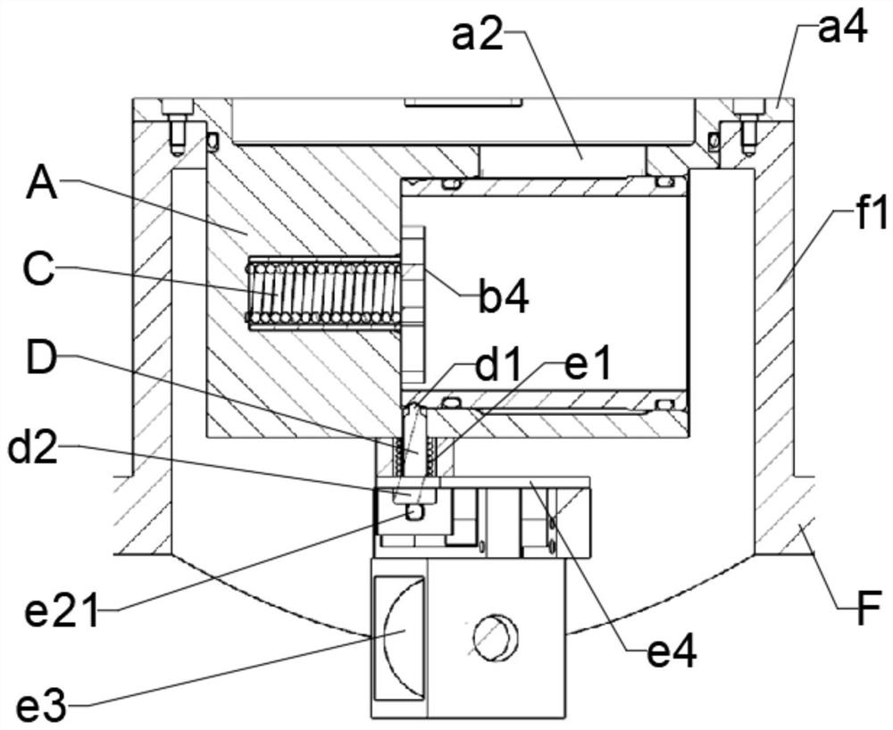
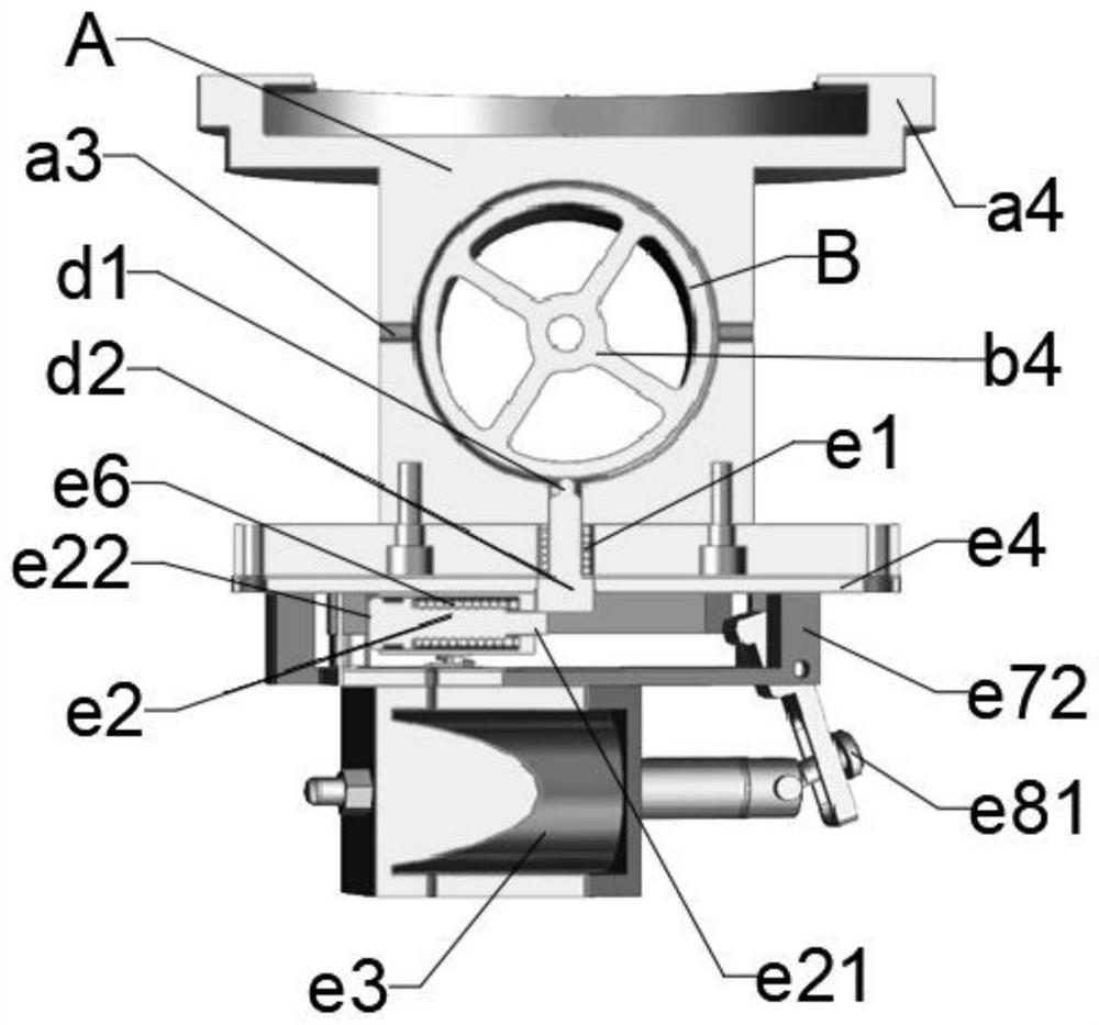
[0049]A water inlet device, including a device body, a sealing member, an elastic member for releasing the sealing, a stop pin and an unlocking mechanism;

[0050] The seal is an axially extending part;

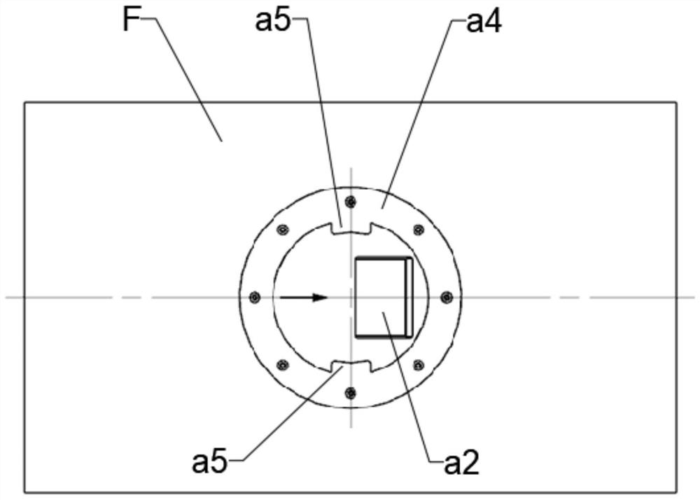
[0051] The main body of the device has a block-shaped structure as a whole, and the outer surface of the main body of the device is provided with a sealing member installation hole for the sealing member to be inserted in its axial direction; the water inlet; the water inlet is blocked and sealed by the seal;

[0052] The side wall of the seal mounting hole is provided with a stop pin insertion hole which penetrates radially and is inserted with the stop pin; the radial inner side of the stop pin is an insertion limit section, and the insertion limit The segment is inserted into the correspondi...


PUM


Abstract

The invention discloses a water inlet device, comprising a device main body, a sealing member, an elastic member for unsealing, a stop pin and an unlocking mechanism; the sealing member is characterized in that the sealing member is a cylindrical structure as a whole, and the axial direction of the sealing member is close to two The positions of the end faces are two sealing ends, and the outer sides of the two sealing ends are provided with at least one sealing groove equipped with an O-ring; The sealing of the water inlet; the position between the two sealing ends on the sealing element is the water inlet section with an outer diameter smaller than the two sealing ends, and the water inlet on the main body of the device is communicated with the annular space on the outer periphery of the water inlet section; the stopper on the sealing element The limiting structure is arranged at the position between the sealing groove and the adjacent end face; the device body is provided with an elastic member for releasing the sealing for pushing or pulling the sealing member. The invention also discloses the installation structure of the above water inlet device. The invention has the advantages of low noise, good privacy, environmental protection and the like.

Description

technical field [0001] The invention belongs to the field of underwater equipment, in particular to a water inlet device and an installation structure thereof. Background technique [0002] The water inlet device can be used for military or civilian underwater robots, underwater vehicles or underwater deployment systems. For example, an application scenario is: when the underwater vehicle does not need to be recovered after performing the task, it can be sunk through the water inlet device. For example, another application scenario is: after the underwater deployment system is deployed, in order to ensure the balance of the system, such as entering water in the cabin, to compensate for the weight loss of the deployed objects separated from the underwater deployment system, ensuring that The underwater deployment system can continue to sail or recover reliably. [0003] There are two kinds of water inlet devices commonly used at present: one is the method of using pyrotechn...

Claims


Application Information

Patent Timeline
Patent Type & Authority Patents(China)
IPC IPC(8): B63G8/22B63G8/26B63C11/52
CPCB63G8/22B63G8/26B63C11/52Y02E10/20
Inventor 叶天源谭双妮李志文邹磊吴鑫胡宇航凌晨
Owner CHONGQING QIANWEI SCI & TECH GRP
Why Eureka
Try Eureka