Supercharge Your Innovation With Domain-Expert AI Agents!

Display device

A display device and display module technology, applied in the direction of instruments, electrical digital data processing, data processing input/output process, etc., can solve the problem of affecting panel operation, unfavorable appearance, and non-continuity of reflection spectrum distribution between display area and non-display area Sex and other issues, to improve visual comfort, reduce the effect of reflected light interference

Pending Publication Date: 2021-12-24
HENGHAO TECH CO LTD
View PDF0 Cites 0 Cited by
  • Summary
  • Abstract
  • Description
  • Claims
  • Application Information

AI Technical Summary

Problems solved by technology

For example, the average reflection difference of visible light between the display area and the non-display area of ​​the existing display device or the display device including the touch module is greater than 3%, and the visible light passing through the display area and the non-display area respectively The CIE chromaticity difference is greater than 3
Therefore, the reflection spectrum distribution of the display area and the non-display area of ​​the existing display device is not continuous, therefore, the display area and the non-display area can be clearly distinguished visually, which is not conducive to aesthetics.
In addition, if the reflectance of the display device is not treated to reduce the reflection, the reflectance will generally be high, and the user is more likely to be visually disturbed by the reflected light from the background ambient light source, which will affect the operation of the panel

Method used


Image

  • Display device
  • Display device
  • Display device

Examples


Embodiment Construction

[0027] Reference will now be made in detail to the exemplary embodiments of the present invention, examples of which are illustrated in the accompanying drawings. Wherever possible, the same reference numbers will be used in the drawings and description to refer to the same or like parts.

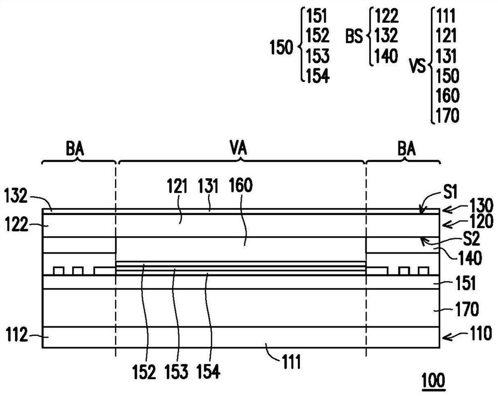
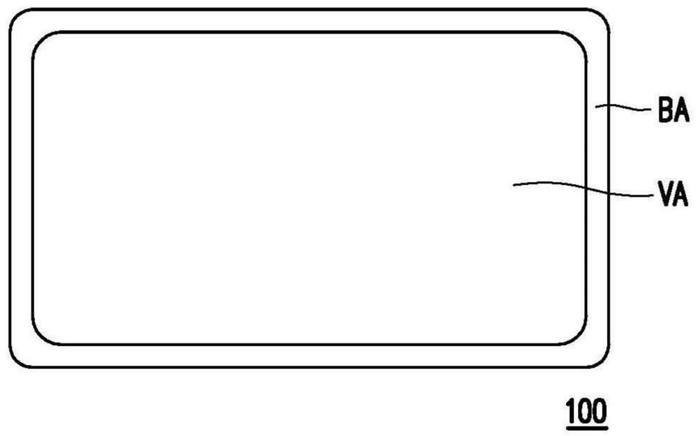
[0028] Figure 1A is a schematic structural diagram of a display device according to an embodiment of the present invention. Figure 1B is a schematic front view of a display device according to an embodiment of the present invention. Please refer to Figure 1A and Figure 1B , in this embodiment, the display device 100 has a visible area VA and a non-visible area BA, wherein the non-visible area BA surrounds the visible area VA. The display device 100 includes a first stack structure VS and a second stack structure BS. The first stacked structure VS is located in the visible area VA, and the second stacked structure BS is located in the non-visible area BA. More specifically, as Figur...


PUM

PropertyMeasurementUnit
reflectanceaaaaaaaaaa

Abstract

The invention provides a display device which has good chromaticity consistency and good visual comfort. The display device has a visible area and a non-visible area. The display device comprises a first laminated structure and a second laminated structure. The first laminated structure is located in the visible area. The second laminated structure is located in the non-visible area. The visible light has a first chromaticity after being reflected by the first laminated structure, the visible light has a second chromaticity after being reflected by the second laminated structure, and the CIE chromaticity difference between the first chromaticity and the second chromaticity is smaller than 3. The first laminated structure has a first average reflectance to visible light, the second laminated structure has a second average reflectance to visible light, and the first average reflectance and the second average reflectance are less than 3%. The display device has an average reflectivity difference value to visible light, and the average reflectivity difference value is smaller than 2%.

Description

technical field [0001] The invention relates to a display device. Background technique [0002] Existing display devices include a display area and a frame area as a non-display area, and the frame area is usually made of black ink. When the display screen of the display device is not lit, the reflectance and chromaticity of the visible light are different in degree between the display area and the non-display area of ​​the display device. For example, the average reflection difference of visible light between the display area and the non-display area of ​​the existing display device or the display device including the touch module is greater than 3%, and the visible light passing through the display area and the non-display area respectively The CIE chromaticity difference value is greater than 3. Therefore, the reflection spectrum distribution of the display area and the non-display area of ​​the existing display device is not continuous, so the display area and the non-...

Claims


Application Information

Patent Timeline
Patent Type & Authority Applications(China)
IPC IPC(8): G06F3/041
CPCG06F3/0412
Inventor 蔡文荣蔡清裕蔡惠蓉陈冠仁陈煜东
Owner HENGHAO TECH CO LTD
Features
  • R&D
  • Intellectual Property
  • Life Sciences
  • Materials
  • Tech Scout
  • Unparalleled Data Quality
  • Higher Quality Content
  • 60% Fewer Hallucinations
Learn More