

Infusion support for nursing
A technology of infusion stand and insertion rod, which is applied in the field of medical care, can solve the problems of limited number of infusion bottles, high frequency of use of infusion stand, adverse effects on the body, etc., and achieve the effect of increasing stability and increasing the number of placements
- Summary
- Abstract
- Description
- Claims
- Application Information
AI Technical Summary
Problems solved by technology
Method used
Image

Examples
Embodiment 1
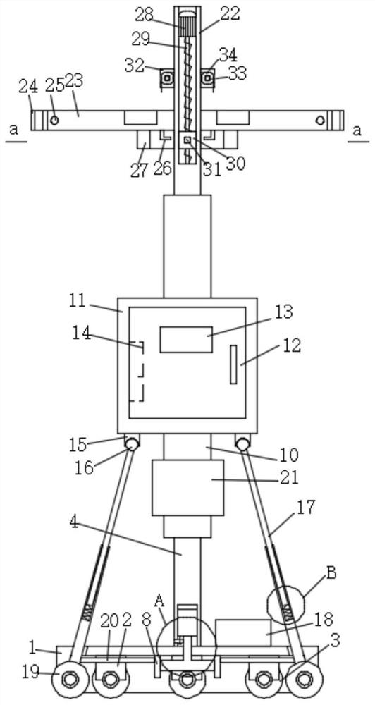
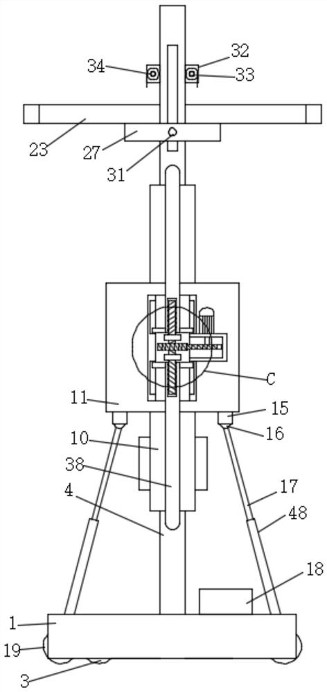
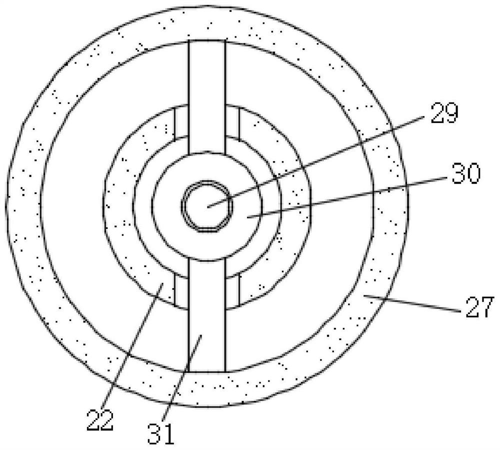
[0027] see Figure 1-10 , an infusion stand for nursing, comprising a base 1, a lower insertion rod 4, two rod sleeves 10 and an upper insertion rod 22, a wheel seat 2 is fixedly installed on the bottom end of the base 1, and a universal wheel is installed on the wheel seat 2 for rotation 3. The universal wheels 3 are distributed in a circular array along the base 1, and the number of installations is three. There is a socket in the middle of the base 1, and the inner wall of the socket is fixedly installed with the lower insertion rod 4, the lower insertion rod 4 and the upper insertion rod 22. Adjacent sides are respectively installed in two rod sleeves 10, and the adjacent sides of the two rod sleeves 10 are fixedly connected with the same thermostat 11, and the two rod sleeves 10 are respectively fixedly inserted with a core rod 37, an upper insertion rod 22 and The lower inserting rods 4 are respectively inserted into the two rod sleeves 10, and respectively sleeved on th...
Embodiment 2
[0033] see Figure 1-10 , an infusion stand for nursing, comprising a base 1, a lower insertion rod 4, two rod sleeves 10 and an upper insertion rod 22, a wheel seat 2 is fixedly installed on the bottom end of the base 1, and a universal wheel is installed on the wheel seat 2 for rotation 3. The universal wheels 3 are distributed in a circular array along the base 1, and the number of installations is three. There is a socket in the middle of the base 1, and the inner wall of the socket is fixedly installed with the lower insertion rod 4, the lower insertion rod 4 and the upper insertion rod 22. Adjacent sides are respectively installed in two rod sleeves 10, and the adjacent sides of the two rod sleeves 10 are fixedly connected with the same thermostat 11, and the two rod sleeves 10 are respectively fixedly inserted with a core rod 37, an upper insertion rod 22 and The lower inserting rods 4 are respectively inserted into the two rod sleeves 10, and respectively sleeved on th...
PUM
 Abstract
Description
Claims
Application Information