Optical imaging lens

A technology of optical imaging lens and diffractive optical element, which is applied in the direction of optics, optical elements, instruments, etc., and can solve problems such as poor imaging quality

Pending Publication Date: 2022-01-04
ZHEJIANG SUNNY OPTICAL CO LTD
View PDF0 Cites 0 Cited by
  • Summary
  • Abstract
  • Description
  • Claims
  • Application Information

AI Technical Summary

Problems solved by technology

[0004] The main purpose of the present invention is to provide an optical imaging lens t

Method used


Image

  • Optical imaging lens
  • Optical imaging lens
  • Optical imaging lens

Examples


Embodiment 1

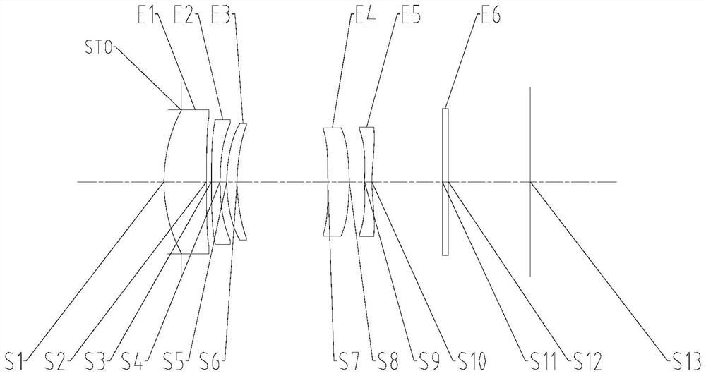
[0057] Such as Figure 1 to Figure 19 As shown, the optical imaging lens includes a first lens, a second lens, a third lens, a fourth lens and a fifth lens, the first lens has a positive power, and the object side of the first lens is a convex surface; the second lens has a negative light power, the image side of the second lens is concave; the third lens has power, the object side of the third lens is convex; the fourth lens has positive power, and the image side of the fourth lens is convex; the fifth lens has Negative refractive power, the object side of the fifth lens is convex, and the image side of the fifth lens is concave; among the first lens to the third lens, at least one lens has a diffractive optical element on one surface, and the diffractive optical element is opposite to The diffraction efficiency of light with a waveband in the range of 470nm-650nm is greater than 80%; the on-axis distance TTL from the object side of the first lens to the imaging surface of th...

Embodiment 2

[0074] Such as Figure 1 to Figure 19As shown, the optical imaging lens includes a first lens, a second lens, a third lens, a fourth lens and a fifth lens, the first lens has a positive power, and the object side of the first lens is a convex surface; the second lens has a negative light power, the image side of the second lens is concave; the third lens has power, the object side of the third lens is convex; the fourth lens has positive power, and the image side of the fourth lens is convex; the fifth lens has Negative refractive power, the object side of the fifth lens is convex, and the image side of the fifth lens is concave; among the first lens to the third lens, at least one lens has a diffractive optical element on one surface, and the diffractive optical element is opposite to The diffraction efficiency of light with a wave band in the range of 470nm-650nm is greater than 80%; the on-axis distance TTL from the object side of the first lens to the imaging surface of th...


PUM


Abstract

The invention provides an optical imaging lens, which is characterized in that a first lens has positive focal power, the object side surface of the first lens is a convex surface, a second lens has negative focal power, the image side surface of the second lens is a concave surface, a third lens has focal power, the object side surface of the third lens is a convex surface, a fourth lens has positive focal power, the image side surface of the fourth lens is a convex surface, a fifth lens has negative focal power, the object side surface of the fifth lens is a convex surface, the image side surface of the fifth lens is a concave surface, in the first lens, the second lens, the third lens and the third lens, a diffractive optical element is arranged on one surface of at least one lens, and the diffraction efficiency of the diffractive optical element on light with the wave band ranging from 470 nm to 650 nm is larger than 80%, and the on-axis distance TTL from the object side surface of the first lens to the imaging surface of the optical imaging lens and the effective focal length f of the optical imaging lens meet the condition that TTL/f is smaller than 0.95. According to the invention, the problem that in the prior art, an optical imaging lens is poor in imaging quality is solved.

Description

technical field [0001] The present invention relates to the technical field of optical imaging equipment, in particular to an optical imaging lens. Background technique [0002] In recent years, with the rapid development of electronic terminal equipment such as smart phones, consumers have higher and higher demands for miniaturization, ultra-thinness and high imaging quality of camera equipment. As an important aberration affecting imaging quality, chromatic aberration is usually caused by optical materials having different refractive indices for different colors of light. Excessive chromatic aberration can easily affect the imaging quality of optical imaging lenses, resulting in poor imaging quality of optical imaging lenses. [0003] That is to say, the optical imaging lens in the prior art has the problem of poor imaging quality. Contents of the invention [0004] The main purpose of the present invention is to provide an optical imaging lens to solve the problem of p...

Claims


Application Information

Patent Timeline
IPC IPC(8): G02B13/00G02B13/18
CPCG02B13/0045G02B13/0055G02B13/18
Inventor 龙思琛徐武超国成立戴付建赵烈烽
Owner ZHEJIANG SUNNY OPTICAL CO LTD
Why Eureka
Try Eureka