Optical imaging lens

An optical imaging lens, diffractive optical element technology, applied in optics, optical elements, instruments, etc., can solve the problems of high imaging quality and miniaturization

Pending Publication Date: 2022-01-04
ZHEJIANG SUNNY OPTICAL CO LTD
View PDF0 Cites 0 Cited by
  • Summary
  • Abstract
  • Description
  • Claims
  • Application Information

AI Technical Summary

Problems solved by technology

[0004] The main purpose of the present invention is to provide an optical imaging lens to solve the problem of high imaging quality and miniaturization in the optical imaging lens in the prior art.

Method used


Image

  • Optical imaging lens
  • Optical imaging lens
  • Optical imaging lens

Examples


Embodiment 1

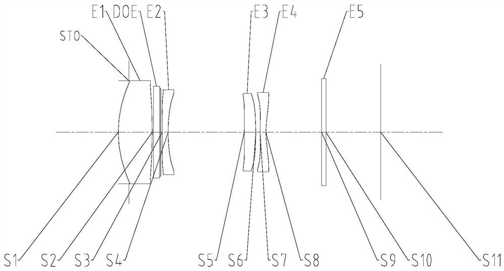
[0052] Such as Figure 1 to Figure 17 As shown, along the optical axis of the optical imaging lens, the optical imaging lens includes a first lens, a diffractive optical element, a second lens, a third lens and a fourth lens in sequence from the object side to the image side of the optical imaging lens, and the first lens has a positive refractive power , the object side of the first lens is a convex surface; the diffraction efficiency of the diffractive optical element to light with a wavelength in the range of 470nm to 650nm is greater than 80%; the second lens has negative refractive power, and the image side of the second lens is concave; the third The lens has positive refractive power; the fourth lens has negative refractive power, the object side of the fourth lens is convex, and the image side of the fourth lens is concave; the effective focal length f of the optical imaging lens is the same as the object side of the first lens to the optical imaging The on-axis distan...

Embodiment 2

[0066] Such as Figure 1 to Figure 17 As shown, along the optical axis of the optical imaging lens, the optical imaging lens includes: a first lens, a diffractive optical element, a second lens, a third lens and a fourth lens in order from the object side to the image side of the optical imaging lens, and the first lens has positive optical focus degree, the object side of the first lens is a convex surface; the diffraction efficiency of the diffractive optical element to light with a wavelength in the range of 470nm to 650nm is greater than 80%; the second lens has negative refractive power, and the image side of the second lens is concave; The three lenses have positive refractive power; the fourth lens has negative refractive power, the object side of the fourth lens is convex, and the image side of the fourth lens is concave; the central thickness CT1 of the first lens, the central thickness CT2 of the second lens, Between the central thickness CT3 of the third lens and th...


PUM


Abstract

The invention provides an optical imaging lens, which sequentially comprises,along the optical axis of the optical imaging lens from the object side to the image side of the optical imaging lens, a first lens, wherein the first lens has positive focal power, and the object side surface of the first lens is a convex surface; a diffractive optical element, wherein the diffraction efficiency of the diffractive optical element on light with a wavelength ranging from 470 nm to 650 nm is larger than 80%; a second lens, wherein the second lens has negative focal power, and the image side surface of the second lens is a concave surface; a third lens, wherein the third lens has positive focal power; and a fourth lens, wherein the fourth lens has negative focal power, the object side surface of the fourth lens is a convex surface, the image side surface of the fourth lens is a concave surface, and the effective focal length f of the optical imaging lens and the on-axis distance TTL from the object side face of the first lens to the imaging face of the optical imaging lens meet the condition that f2 / TTL is larger than 15 mm and smaller than 17 mm. According to the invention, the optical imaging lens solves the problem that the optical imaging lens in the prior art cannot give consideration to both high imaging quality and miniaturization.

Description

technical field [0001] The present invention relates to the technical field of optical imaging equipment, in particular to an optical imaging lens. Background technique [0002] With the rapid development of portable smart camera devices such as smart phones, the camera function with high image quality is increasingly favored by consumers. As an important factor affecting image quality, chromatic aberration is usually corrected by combining positive and negative lenses. While optimizing the chromatic aberration and improving the imaging quality, this method also increases the number of lenses of the imaging lens, thereby limiting the ultra-thinning of the imaging lens. [0003] That is to say, there is a problem that high imaging quality and miniaturization cannot be balanced in the optical imaging lens in the prior art. Contents of the invention [0004] The main purpose of the present invention is to provide an optical imaging lens to solve the problem of high imaging ...

Claims


Application Information

Patent Timeline
IPC IPC(8): G02B13/00G02B13/18
CPCG02B13/004G02B13/0055G02B13/18
Inventor 龙思琛徐武超国成立戴付建赵烈烽
Owner ZHEJIANG SUNNY OPTICAL CO LTD
Why Eureka
Try Eureka