
Gushing arm assembly and dish washing machine with same

A spray arm assembly and dishwasher technology, which is applied in the direction of tableware washing machine/rinsing machine, tableware washing machine/rinsing and rinsing machine parts, household utensils, etc., can solve the serious pressure relief of double-layer spray arms and reduce the double-layer The structure of the spray arm affects the washing effect of the tableware in the dishwasher, and the sliding friction resistance between the spray arm and the spray arm seat is large, etc.

Active Publication Date: 2022-01-11
FOSHAN SHUNDE MIDEA WASHING APPLIANCES MFG CO LTD
View PDF8 Cites 0 Cited by
  • Summary
  • Abstract
  • Description
  • Claims
  • Application Information

AI Technical Summary

Problems solved by technology

[0006] 1) In the conventional single-layer spray arm structure, the spray arm and the spray arm seat are connected by buckles. Since the two need to rotate relative to each other, there is a certain gap between the two, causing part of the water to leak through this gap. In addition, the sliding frictional resistance during the relative movement between the spray arm and the spray arm seat is relatively large
[0007] 2) In the double-layer spray arm structure, the lower spray arm and the spray arm seat, the upper spray arm and the lower spray arm are all connected by buckles, resulting in serious pressure relief of the double-layer spray arm, and the frictional resistance when rotating is relatively large. Thereby greatly reducing the cleaning effect of the double-layer spray arm structure on the tableware in the dishwasher

Method used


Image

  • Gushing arm assembly and dish washing machine with same
  • Gushing arm assembly and dish washing machine with same
  • Gushing arm assembly and dish washing machine with same

Examples


Embodiment Construction

[0038] Exemplary embodiments of the present disclosure will be described in more detail below with reference to the accompanying drawings. Although exemplary embodiments of the present disclosure are shown in the drawings, it should be understood that the present disclosure may be embodied in various forms and should not be limited by the embodiments set forth herein. Rather, these embodiments are provided for more thorough understanding of the present disclosure and to fully convey the scope of the present disclosure to those skilled in the art. It should be noted that the application of the spray arm assembly to the dishwasher in the present invention is only a preferred embodiment of the present invention, and is not a limitation of the scope of application of the spray arm assembly of the present invention. For example, the spray arm assembly of the present invention is applied to other washing equipment, This adjustment belongs to the scope of protection of the spray arm ...


PUM


Abstract

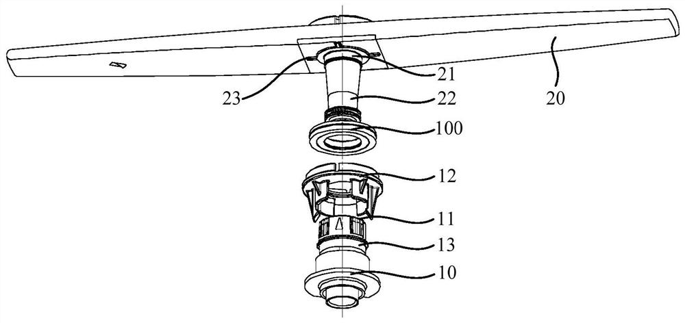
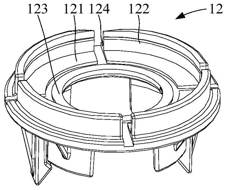
The invention relates to a gushing arm assembly which is used for a dishwasher and comprises a gushing arm seat; a supporting seat which is connected to the gushing arm seat; a first gushing arm which is arranged on the supporting seat in a sleeving manner and is communicated with the gushing arm seat; a first bearing which comprises a first sliding ring and a second sliding ring which can slide relative to each other; the first gushing arm is provided with a first water inlet and a first flow guide pipe located on the periphery of the first water inlet, the first sliding ring is arranged on the outer wall of the first flow guide pipe in a sleeving mode, and the second sliding ring is arranged on the inner wall of the supporting base and located outside the first sliding ring, a first annular protrusion is arranged on the inner wall of the first sliding ring, a first annular groove is formed in the outer wall of the first flow guide pipe, and / or a second annular protrusion is arranged on the outer wall of the second sliding ring, a second annular groove is formed in the inner wall of the supporting seat, and the first gushing arm can rotate relative to the gushing arm seat through the first sliding ring and the second sliding ring. According to the gushing arm assembly, the first gushing arm is connected with the gushing arm base through the first bearing, and therefore friction resistance is reduced.

Description

[0001] This application is a divisional application of an invention patent application filed on March 27, 2019, with application number 201910240001.6, and the title of the invention is "spray arm assembly and dishwasher with same". technical field [0002] The invention relates to the technical field of kitchen supplies, in particular to a spray arm assembly and a dishwasher with the same. Background technique [0003] This section provides background information related to the present disclosure only and is not necessarily prior art. [0004] With the improvement of material living standards, dishwashers that can free hands are gradually becoming the standard equipment for quality life. Compared with traditional hand washing, dishwashers have the advantages of clean washing, sterilization, water saving and labor saving. Household dishwashers generally adopt the spray washing method. Driven by the washing pump, the water flow sprays and scours the surface of the tableware ...

Claims


Application Information

Patent Timeline
Patent Type & Authority Applications(China)
IPC IPC(8): A47L15/22A47L15/42
CPCA47L15/22A47L15/428A47L15/4217Y02B40/00
Inventor 张婧宜费望春蔡思琦
Owner FOSHAN SHUNDE MIDEA WASHING APPLIANCES MFG CO LTD
Learn More