Intelligent-based automatic cutting machine capable of achieving online monitoring

A cutting machine, automatic technology, applied in the direction of automatic control devices, metal processing machinery parts, maintenance and safety accessories, etc., can solve the problem of not having the function of cutting angle adjustment, and achieve the effect of easy online observation and easy observation

Pending Publication Date: 2022-01-11
苏州万恒自动化科技有限公司
View PDF5 Cites 0 Cited by
  • Summary
  • Abstract
  • Description
  • Claims
  • Application Information

AI Technical Summary

Problems solved by technology

[0004] The purpose of the present invention is to provide a kind of automatic cutting machine based on intelligence that can be monitored online, so as to solve the problem that the function of cutting angle adjustment is not provided in the above-mentioned background technology

Method used


Image

  • Intelligent-based automatic cutting machine capable of achieving online monitoring
  • Intelligent-based automatic cutting machine capable of achieving online monitoring
  • Intelligent-based automatic cutting machine capable of achieving online monitoring

Examples


Embodiment 1

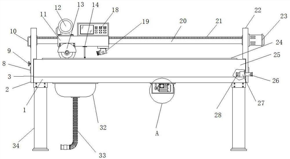
[0028] Example 1: See Figure 1-6 , a kind of automatic cutting machine based on intelligence that can be monitored online, including a frame body 1, the top of the frame body 1 is fixedly connected with a coaming plate 25, and the two sides of the bottom end of the frame body 1 are respectively equipped with supporting legs 34, and the sides of the coaming plate 25 One side is provided with the left side plate 2, the other side of the enclosure 25 is provided with the right side plate 22, the top of the frame body 1 is provided with the base 11, one side of the bottom end of the base 11 is provided with a camera 19, the left side plate 2 Between one side of the right side plate 22 and the laterally fixedly connected slide shaft 20, between the left side plate 2 and one side of the right side plate 22 is horizontally movably connected with the threaded shaft 21, and one side of the right side plate 22 is installed with the first A servo motor 23, the output end of the first se...

Embodiment 2

[0032] Embodiment 2: The inside of the fixed seat 3 is provided with a plurality of sets of limit holes 6, one side of the fixed seat 3 is etched with a scale pattern 7, one side of the left side plate 2 is horizontally inserted with a limit knob 9, and the left side plate 2- The interior of the side is provided with an observation window 35;

[0033] The shape and size of one side of the limit knob 9 matches the shape and size of the limit hole 6, the external thread of the limit knob 9 matches the internal thread of the limit hole 6, and the position of the observation window 35 corresponds to the position of the scale pattern 7. It is convenient to observe in time and choose a suitable angle for fixing;

[0034] Specifically, such as Figure 5 and Image 6As shown, the user can pass through the rotation angle through the observation window 35. When reaching a suitable angle, tighten the limit knob 9, and the limit knob 9 snaps into the limit hole 6 to complete the angle f...

Embodiment 3

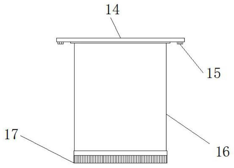
[0035] Embodiment 3: The base plate 14 is fixedly connected to the middle position of the bottom end of the base 11, and two sets of mounting bolts 15 are inserted vertically inside the bottom end of the base plate 14. The bottom end of the plate 16 is glued with a soft brush 17;

[0036] The installation bolts 15 are distributed symmetrically about the vertical center line of the base plate 14, and the installation is more stable;

[0037] Specifically, such as figure 1 and figure 2 As shown, in the cutting process, as the first servo motor 23 drives the threaded shaft 21 to rotate, the base 11 moves left and right along the sliding shaft 20, and the driving motor 12 drives the cutting disc 13 to cut the material, and the dust generated by cutting The stain is blocked by the dust shielding plate 16, and along with the left and right movement of the base 11, the soft brush 17 cleans the dust and impurities on the cutting edge in time, which is convenient for the online obse...


PUM


Abstract

The invention discloses an intelligent-based automatic cutting machine capable of achieving online monitoring, which comprises a frame body, wherein a base is arranged above the frame body, a camera is arranged on one side of the bottom end of the base, and a cutting angle adjusting structure is arranged on one side of a surrounding plate. According to the intelligent-based automatic cutting machine capable of achieving online monitoring, through the arrangement of a fixing base, an extension shaft, a ball bearing, a limiting hole, scale lines, a fixing rotating shaft, a limiting rotary knob, a handle and an observation window, during use, when a cutting angle needs to be adjusted, a user holds the handle with one hand to stabilize the angle and then unscrews the limiting rotary knob, the limiting rotary knob is pulled out of the limiting hole; at the moment, the handle is pulled, a left side plate rotates with the circle center of the fixing base as the midpoint; when a proper angle is reached, the limiting rotary knob is tightened, the limiting rotary knob is clamped into the limiting hole to complete angle fixing, so that the function of adjusting the cutting angle is achieved, and the problem that the device does not have the function of adjusting the cutting angle is solved.

Description

technical field [0001] The invention relates to the technical field of cutting machines, in particular to an intelligent online monitoring automatic cutting machine. Background technique [0002] With the continuous development of the Internet of Things and computer technology, the concept of Internet of Everything runs through various fields of production and life, such as adding intelligent modules to automatic cutting machines, and timely observing the cutting status and material shape through online monitoring. Currently on the market Most of the common automatic cutting machines have similar structures, and now there is a need for an automatic cutting machine that is easy to adjust the cutting angle during use, but there are certain defects in the existing automatic cutting machines: [0003] During the use of the existing automatic cutting machine, if the cutting angle is fixed, or only one angle can be adjusted, there are limitations in cutting. Secondly, in the monit...

Claims


Application Information

Patent Timeline
Patent Type & Authority Applications(China)
IPC IPC(8): B23Q15/26B23Q11/00B23Q11/08
CPCB23Q15/26B23Q11/0042B23Q11/08
Inventor 金健张明璐李建中
Owner 苏州万恒自动化科技有限公司
Why Eureka
Try Eureka