
Differential rope take-up device

A technology of differential speed and rope pulley, which is applied in the field of devices for differential speed rope receiving occasions

Pending Publication Date: 2022-01-11
GUILIN UNIV OF ELECTRONIC TECH
View PDF0 Cites 0 Cited by
  • Summary
  • Abstract
  • Description
  • Claims
  • Application Information

AI Technical Summary

Problems solved by technology

For some special occasions, such as when it is necessary to use two ropes to draw the rope at any differential speed without synchronism, the traditional rope taking method cannot meet this situation.

Method used


Image

  • Differential rope take-up device
  • Differential rope take-up device
  • Differential rope take-up device

Examples


Embodiment Construction

[0018] The present invention will be further described below in conjunction with the accompanying drawings.

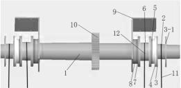
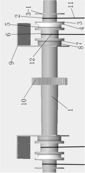
[0019] The differential rope receiving device of the present invention is mainly composed of a specially designed electromagnetic clutch, a shaft, a gear, a catch, and a rope, wherein the material used for the stepped shaft is Q275, and the material used for the gear is 40Cr.

[0020] When the motor is working, it drives the gear to rotate, thereby driving the shaft to rotate, and the rope fixed on the shaft will be retracted and released according to the positive and negative rotation of the motor.

[0021] There is a bayonet pin for tying the rope on the rope receiving wheel.

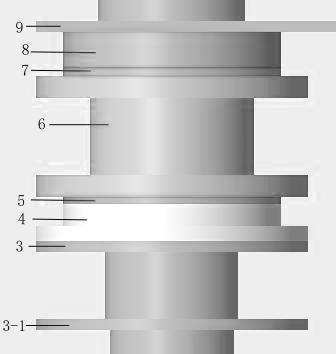
[0022] There are threaded holes on both sides of the rope receiving wheel, and two suction cups are connected with the rope receiving wheel by screws.

[0023] Such as image 3 As shown, the ropes (105, 106) are connected to the specially designed electromagnetic clutch, the ropes (103, 104)...


PUM


Abstract

The invention provides a differential rope take-up device. The differential rope take-up device comprises a specially-designed electromagnetic clutch, a check ring, a shaft and a rope. The electromagnetic clutch comprises two suction cups, two electromagnets, a rope take-up wheel and a fixed plate. One rope is wound on the shaft to be fixedly wound, and the other rope is wound on the rope take-up wheel. The suction cups are installed at the two ends of the rope take-up wheel and used for attraction of the electromagnets at the two ends during working. The check ring is used for preventing the rope from overflowing. The electromagnet on the outer side is connected with the shaft through a key, the electromagnet on the inner side is not provided with a key and is connected with the fixed plate, and the fixed plate is fixed on the box body. After the electromagnet with the key on the outer side is electrified, the rope take-up wheel is attracted, and the rope take-up wheel and the main shaft can rotate together. The key-free electromagnet on the inner side is responsible for keeping the current state of the rope take-up wheel, and when the rope take-up wheel does not work, the current state needs to be kept, and the rope is prevented from reversing. Therefore, the purpose of differential rope take-up can be achieved. The device has the advantages of being simple in structure, convenient to disassemble and assemble and high in universality.

Description

technical field [0001] The invention relates to a device suitable for the occasion of differential speed rope receiving. Background technique [0002] In the prior art, the rope is generally taken in at a constant speed, in other words, a rope or a plurality of ropes are taken together simultaneously, and there is no differential speed rope take-up device. For some special occasions, such as needing to use two ropes, when taking in the rope at any differential speed that is not synchronous, the traditional method of taking in the rope cannot satisfy this situation at this moment. So in order to solve this problem, a kind of device with differential speed receiving rope is designed. Contents of the invention [0003] The object of the present invention is to provide a differential speed rope receiving device, which solves the problem of stability when the parallelogram structure crosses the dead point for ascending or descending movement. The device has the advantages of s...

Claims


Application Information

Patent Timeline
IPC IPC(8): B65H75/38B65H75/44
CPCB65H75/38B65H75/4418B65H75/44B65H2701/35
Inventor 范冰陈坤孙茗轩曹真飞
Owner GUILIN UNIV OF ELECTRONIC TECH
Learn More