Proximity switch detection device and detection method thereof

A technology of proximity switch and detection device, applied in the direction of circuit breaker testing, etc., can solve the problem of not being able to enter the sensing area, and achieve the effect of reducing the degree of cooperation, reducing requirements, and reducing power devices

Active Publication Date: 2022-01-11
山东天大清源信息科技有限公司
View PDF32 Cites 2 Cited by
  • Summary
  • Abstract
  • Description
  • Claims
  • Application Information

AI Technical Summary

Problems solved by technology

[0003] The purpose of this application is to provide a proximity switch detection device and its detection method, which solves the problem that the existing detection devices cannot enter the sensing area from different directions, and ensures the accuracy of the detection results

Method used


Image

  • Proximity switch detection device and detection method thereof
  • Proximity switch detection device and detection method thereof
  • Proximity switch detection device and detection method thereof

Examples


Embodiment 1

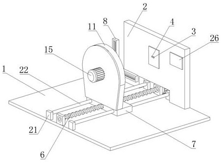
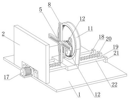
[0026] Embodiment 1: A kind of proximity switch detection device, comprises detection platform 1, is provided with detection board 2 on detection platform 1, is integrated with controller, counter, display screen 26 on detection board 2, is also provided with detection board 2 The switch 3 and the distance measuring device 4, preferably, the distance measuring device 4 selects a laser range finder for measuring the distance between the detection switch 3 and the sensing block 5 . The detection platform 1 is provided with a first driving device 6, the first driving device 6 includes a second motor 17, the second motor 17 is fixed on the detection platform 1, the output shaft of the second motor 17 is connected with a lead screw 18, and the detection platform 1 is provided with two first fixed seats 19, and the first fixed seat 19 is provided with a first bearing 20, and the two ends of the screw 18 are matched with the two first bearings 20 respectively. Lead screw 18 is provid...

Embodiment 2

[0029] Embodiment 2: a kind of proximity switch detection method comprises the following steps,

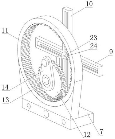
[0030] S1: The sensing block 5 approaches the proximity switch in the axial direction. At this time, a sensing block 5 is located at the center of the cross track 8 until the proximity switch is activated. The distance measuring device 4 measures the effective sensing distance D from the proximity switch to the sensing block 5 at this time. ;

[0031] S2: The meshing gear rotates along the ring gear 11, and the two sensing blocks 5 move along the horizontal rail 9 and the vertical rail 10 respectively, and the proximity switch is triggered to act in the four directions of left, upper, right, and lower, until the proximity switch does not act, and record the distance Proximity switch action times n1;

[0032] S3: The sensing block 5 approaches the proximity switch along the axial direction. At this time, there is a sensing block 5 located at the center of the cross track 8. The mo...


PUM


Abstract

The invention discloses a proximity switch detection device and a detection method thereof, and mainly relates to the field of proximity switch detection devices. The detection device comprises a detection table, a detection plate, a controller and a counter are arranged on the detection table, and a detection switch and a distance measuring device are arranged on the detection plate; an induction block, a first driving device and a second driving device are further arranged on the detection table, the first driving device drives the induction block to axially get close to or get away from the detection switch, and the second driving device drives the induction block to radially get close to or get away from the detection switch; the controller controls the first driving device and the second driving device to drive the sensing block to move; and the counter counts the sensing times of the detection switch. The device has the beneficial effects that the problem that an existing detection device cannot enter an induction area from different directions is solved, and the accuracy of a detection result is ensured.

Description

technical field [0001] The present application relates to the field of proximity switch detection devices, in particular to a proximity switch detection device and a detection method thereof. Background technique [0002] The proximity switch is a position switch that can be operated without direct mechanical contact with the moving parts. When the object approaches the sensing surface of the switch to the action distance, the switch can be activated without mechanical contact and any pressure, thereby driving the DC electric appliance. Or provide control instructions to devices such as PLC. In the debugging and inspection process of the proximity switch, it is necessary to detect the effective sensing distance, durable times, sensitivity, etc. In order to effectively detect the sensitivity of the proximity switch, it is necessary to enter the sensing area from different directions to ensure the reliability of the detection sensitivity data. The existing detection devices ar...

Claims


Application Information

Patent Timeline
Patent Type & Authority Applications(China)
IPC IPC(8): G01R31/327
CPCG01R31/327
Inventor 贾甲孙雅婷
Owner 山东天大清源信息科技有限公司
Why Eureka
Try Eureka