Steel rail surface jacking device

A technology of jacking device and rail, applied in the direction of track, track maintenance, track superstructure, etc., can solve the problems of contact spots, large workload, polygons, etc.

Pending Publication Date: 2022-01-18
EAST CHINA JIAOTONG UNIVERSITY
View PDF0 Cites 0 Cited by
  • Summary
  • Abstract
  • Description
  • Claims
  • Application Information

AI Technical Summary

Problems solved by technology

[0002] With the development of high-speed and heavy-duty railways, various problems occur when the rails are running-in with the wheel sets during use, such as corrugation, polygons, and contact spots. In order to solve the above problems and extend the service life of the rails, it is necessary to The rail surface is inspected, but during the inspection process, since the laid rail is not horizontal, the guide wheel cannot cling to the rail surface when walking, and the rail inspection trolley moves left and right on the rail, resulting in insuff

Method used


Image

  • Steel rail surface jacking device
  • Steel rail surface jacking device

Examples


Embodiment Construction

[0014] Below in conjunction with accompanying drawing and embodiment the present invention is described in further detail:

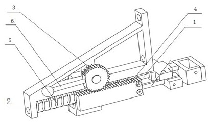
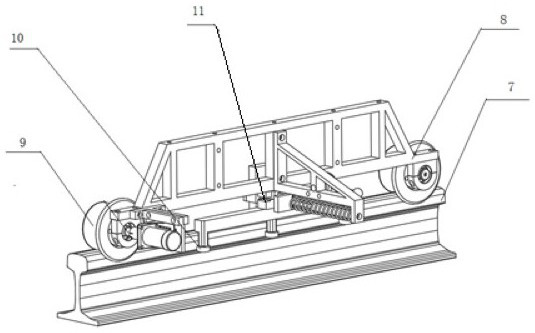
[0015] The specific implementation of the rail surface tightening device of the present invention is as follows: figure 1 , figure 2 As shown, the guide wheel 9 in the spring tensioning device is placed on the inner side of the left rail 7 when in use, and is close to the inner edge of the rail, so that the guide wheel is more stable during walking;

[0016] The sleeve 2 is connected with the slider 11, which can play the role of shock absorption;

[0017] The slide block 11 and the guide wheel 10 mounting seat on the left side rail 7 are connected together, so that the spring clamping device obtains supporting force from the mounting seat;

[0018] When the guide wheel 10 is not in contact with the side of the rail head of the rail 7, the spring moves outward against the sleeve 2 to contact the side of the rail, maintaining the relative perpendicular...


PUM


Abstract

The invention relates to the technical field of track detection, in particular to a steel rail surface jacking device. The steel rail surface jacking device comprises a guide rod 1, a sleeve 2, a gear 3, a rack 4, a spring 5, a handle 6, a steel rail 7, a side beam 8, a guide wheel 9, a guide wheel 10 and a sliding block 11; the guide wheel 9 is arranged on the steel rail, the side beam is arranged on the guide wheel 9, the guide wheel 10 is installed below the side beam, the sleeve 2 is arranged on the guide rod 1, the rack 4 is arranged beside the sleeve 2, and the gear 3 is used in cooperation with the rack 4. The spring is arranged on the outer side of the sleeve 2, and the handle 6 is connected to the gear 3.

Description

technical field [0001] The present invention is a research on the rail surface of the left rail for rail detection: when the rail inspection trolley is walking on the rail, a spring tightening device is used to realize the effect of being tightly attached to the inner rim of the left rail. Background technique [0002] With the development of high-speed and heavy-duty railways, various problems occur when the rails are running-in with the wheel sets during use, such as corrugation, polygons, and contact spots. In order to solve the above problems and extend the service life of the rails, it is necessary to The rail surface is inspected, but during the inspection process, the laid rail is not horizontal, so the guide wheel cannot cling to the rail surface when walking, and the rail inspection trolley moves left and right on the rail, resulting in insufficient stability of the inspection data. At the same time, when the track inspection trolley passes through the gaps between ...

Claims


Application Information

Patent Timeline
IPC IPC(8): E01B35/12
CPCE01B35/12E01B2203/141
Inventor 林凤涛柯露露杨洋邹亮吴涛
Owner EAST CHINA JIAOTONG UNIVERSITY
Why Eureka
Try Eureka