Axial pressure loading reversing device with initial curvature eccentric test piece

A technology for reversing devices and test pieces, which is applied in the direction of measuring devices, testing of mechanical components, testing of machine/structural components, etc., and can solve problems such as unstable loading system, lateral instability of loading system, and damage to test pieces. , to achieve the effect of reducing risk, solving lateral displacement and improving accuracy

Pending Publication Date: 2020-11-24
SHENYANG AIRCRAFT DESIGN INST AVIATION IND CORP OF CHINA
View PDF7 Cites 3 Cited by
  • Summary
  • Abstract
  • Description
  • Claims
  • Application Information

AI Technical Summary

Problems solved by technology

[0003] The axial compression test of ordinary small test pieces is completed on the pressure testing machine. For large and medium-sized test pieces, it cannot be placed in the pressure testing machine. When the ground is axially compressed and loaded, the loading system is prone to lateral instability, especially when the test pieces are belts. When the initial curvature is eccentric, the entire test system becomes a non-centric force system. When the piston rod of the loading actuator is compressed during axial compression loading, the lateral additional bending moment will cause disturbance and lateral displacement, making the entire loading system a An unstable system, and when the piston rod is loaded, it is a moving part and cannot be laterally restrained, so it is difficult to obtain accurate results in the test, and even cause abnormal damage to the test piece, resulting in test failure

Method used


Image

  • Axial pressure loading reversing device with initial curvature eccentric test piece
  • Axial pressure loading reversing device with initial curvature eccentric test piece
  • Axial pressure loading reversing device with initial curvature eccentric test piece

Examples


Embodiment Construction

[0028] In order to make the purpose, technical solution and advantages of the application more clear, the technical solution in the embodiment of the application will be described in more detail below in conjunction with the drawings in the embodiment of the application. In the drawings, the same or similar reference numerals denote the same or similar elements or elements having the same or similar functions throughout. The described embodiments are some, but not all, embodiments of the application. The embodiments described below by referring to the figures are exemplary, and are intended to explain the present application, and should not be construed as limiting the present application. Based on the embodiments in this application, all other embodiments obtained by persons of ordinary skill in the art without creative efforts fall within the protection scope of this application. Embodiments of the present application will be described in detail below in conjunction with th...


PUM


Abstract

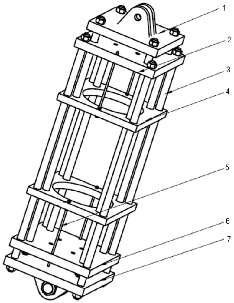
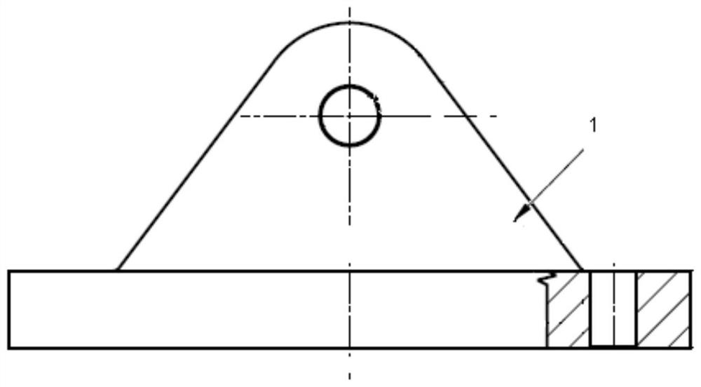
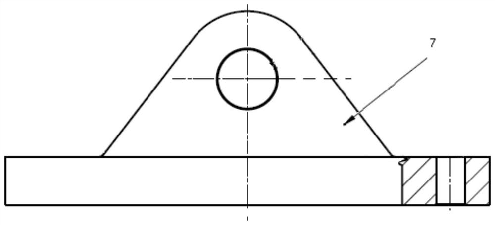
The invention belongs to the field of rear fuselage strength design, and particularly relates to an axial pressure loading reversing device with an initial curvature eccentric test piece. The device comprises a loading joint, a test piece upper end fixing plate, a test piece lower end fixing plate and a supporting joint which are sequentially arranged from top to bottom, the device further comprises sliding rod studs, matched first mounting holes are formed in the loading joint and the test piece lower end fixing plate, and the loading joint is fixedly connected with the test piece lower end fixing plate through a plurality of first sliding rod studs; matched second mounting holes are formed in the test piece upper end fixing plate and the supporting joint; the test piece upper end fixingplate is fixedly connected with the supporting joint through a plurality of second sliding rod studs; the test piece upper end fixing plate is provided with a first through holes for the first slidingrod studs to penetrate through, the test piece lower end fixing plate is provided with second through holes for the second sliding rod studs to penetrate through, and the two ends of the test piece are connected with the test piece upper end fixing plate and the test piece lower end fixing plate respectively. The test system error can be reduced.

Description

technical field [0001] The application belongs to the field of rear fuselage strength design, and in particular relates to an axial pressure loading reversing device with an eccentric test piece of initial curvature. Background technique [0002] With the development of a new generation of aircraft, in order to meet the needs of stealth, loading and ground maintenance, the aircraft platform has undergone major changes in the layout and structure of the fuselage. In order to meet the needs of engine ground maintenance of a certain aircraft, the lower part of the main force transmission frame of the rear fuselage is designed as a structural part with initial curvature eccentricity connected by hinge supports at both ends. For this new structural form and force characteristics , has not occurred in the structural layout of the prior art, especially the axial compression stability of eccentric structural members with initial curvature, and relevant experimental research is requi...

Claims


Application Information

Patent Timeline
Patent Type & Authority Applications(China)
IPC IPC(8): G01M13/00G01N3/04G01N3/08B64F5/60
CPCG01M13/00G01N3/08G01N3/04B64F5/60
Inventor 庞庆辉郭小鹏
Owner SHENYANG AIRCRAFT DESIGN INST AVIATION IND CORP OF CHINA
Why Eureka
Try Eureka