Locking structure for dish washing machine and dish washing machine
A locking structure and dishwasher technology, applied in the washing machine/rinsing machine of tableware, parts of washing machine/rinsing and rinsing machine of tableware, application, etc., can solve the collision between the inner tank and the outer shell, the damage of the magnetic component, the inner tank Poor sealing with the shell and other problems, to achieve the effect of good stability and simple structure
- Summary
- Abstract
- Description
- Claims
- Application Information
AI Technical Summary
Problems solved by technology
Method used
Image
Examples
Embodiment 1
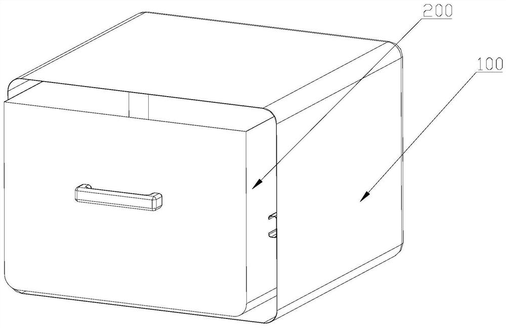
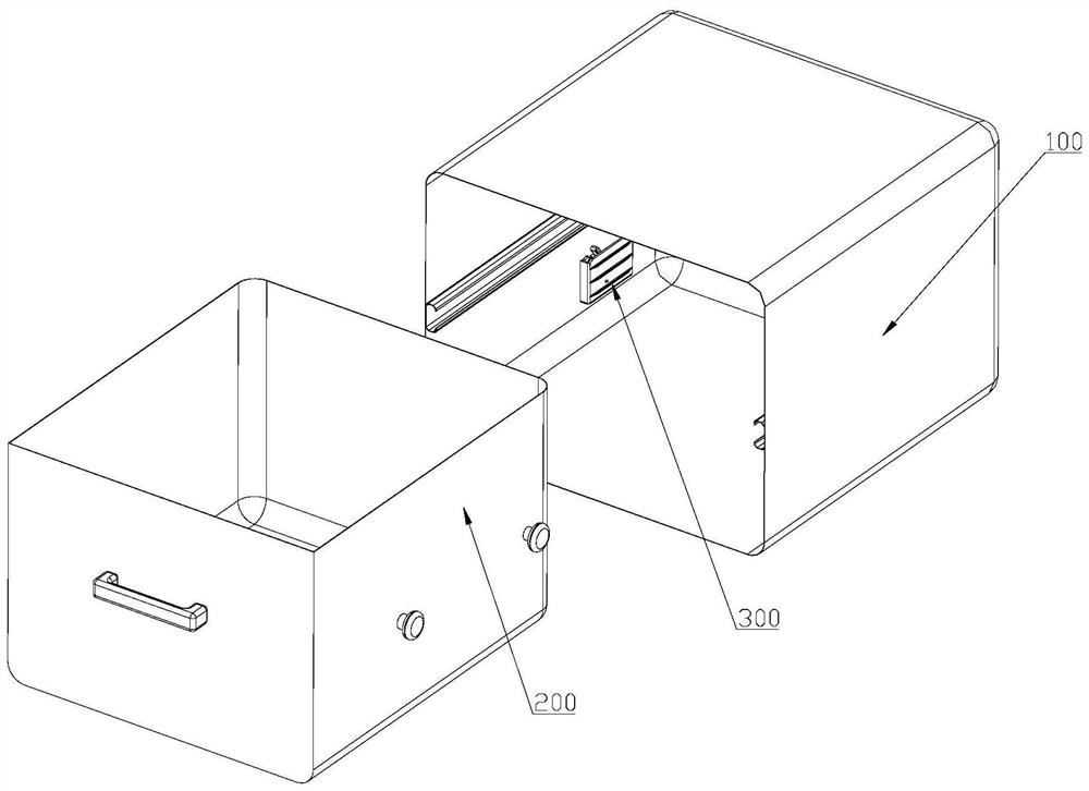
[0046] Such as Figure 1 to Figure 10 As shown, in the embodiment of the present invention, a locking structure 300 for a dishwasher is provided, including a bracket 31, and a swing arm 32 mounted on the bracket 31 that can rotate relative to the bracket 31. The swing arm 32 The lower part is equipped with an elastic member 33 for driving the swing arm 32 to rotate. The upper part of the swing arm 32 is equipped with a claw 34 that can rotate relative to the swing arm 32 . The claw 34 is provided with an accommodating groove 341 opening upward.
[0047] In this embodiment, the elastic member 33 drives the swing arm 32 to rotate, and then the swing arm 32 drives the claw 34 to rotate. The locking structure 300 not only has a simple structure and good stability, but also can precisely control the rotation of the swing arm 32 and the claw 34. Position, so as to ensure that the lock is in place, suitable for popularization and application.
[0048] Such as Figure 1 to Figure 3 ...
Embodiment 2
[0067] Such as Figure 1 to Figure 10 As shown, this embodiment is a further limitation of the first embodiment above. The support 31 includes a vertical support body 311. The support body 311 is provided with a swing arm shaft 314. The swing arm 32 is provided with a support sleeve 323. The swing arm shaft 314 passes through the through hole 325 provided on the swing arm 32 and is loaded into the support sleeve 323. The elastic member 33 is sleeved on the outer wall of the support sleeve 323. The relative bracket 31 rotates around the axis, and the elastic member 33 is sleeved on the support sleeve 323 to keep the swing arm 32 at the first position, or to swing the swing arm 32 to the second position until it stops at the second position.
[0068] Preferably, the support sleeve 323 is a cylindrical sleeve with a simple structure and convenient processing, so that the swing arm shaft 314 is matched with the support sleeve 323 .
[0069] Such as Figure 5 , Figure 7 to Figu...
Embodiment 3
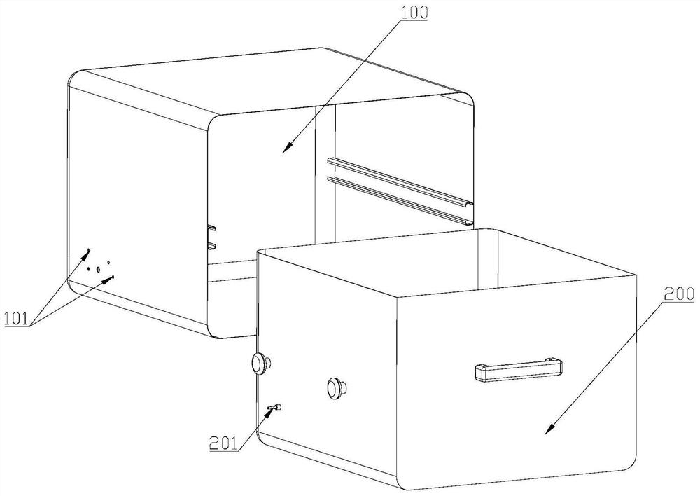
[0076] Such as Figure 1 to Figure 10 As shown, the embodiment of the present invention also provides a dishwasher, including a casing 100, a drawable inner container 200 is provided inside the casing 100, and any locking structure 300 described above, the locking structure The bracket 31 of 300 is installed on the shell 100 , and the inner tank 200 is equipped with a driving rod 21 for rotating the claw 34 , and the driving rod 21 enters the receiving groove 341 from the opening of the receiving groove 341 .
[0077] In this embodiment, the lever 21 moves the claw 34 to separate from the hanging shaft 313, the elastic member 33 drives the swing arm 32 to rotate, and then the swing arm 32 drives the claw 34 to rotate, the locking structure 300 is not only simple in structure and good in stability, It is also possible to precisely control the rotational positions of the swing arm 32 and the claw 34 .
[0078] Such as figure 2 and Figure 8 As shown, in this embodiment, conn...
PUM
 Abstract
Description
Claims
Application Information
 - R&D
- Intellectual Property
- Life Sciences
- Materials
- Tech Scout
- Unparalleled Data Quality
- Higher Quality Content
- 60% Fewer Hallucinations
Browse by: Latest US Patents, China's latest patents, Technical Efficacy Thesaurus, Application Domain, Technology Topic, Popular Technical Reports.
© 2025 PatSnap. All rights reserved.Legal|Privacy policy|Modern Slavery Act Transparency Statement|Sitemap|About US| Contact US: help@patsnap.com


