
Hot plug structure based on NMOS pull-up driver

A hot-swapping and driver technology, applied in the direction of logic circuit coupling/interface, electrical components, logic circuit connection/interface arrangement using field effect transistors, etc., can solve the problem of burning out the buffer circuit and failing to meet the hot-swapping function of the circuit , affecting the bus signal and other issues

Pending Publication Date: 2022-02-01
58TH RES INST OF CETC
View PDF0 Cites 0 Cited by
  • Summary
  • Abstract
  • Description
  • Claims
  • Application Information

AI Technical Summary

Problems solved by technology

However, when the NMOS tube of this connection method is used as the output stage pull-up tube of the buffer circuit, the hot swap function of the circuit cannot be satisfied.
When the output port has a high-level pulse, the output port will flow back to the power supply through the integrated PN junction of the pull-up NMOS transistor substrate, thereby affecting the signal on the bus, and even the generated surge current will burn out the buffer circuit.

Method used


Image

  • Hot plug structure based on NMOS pull-up driver

Examples


Embodiment 1

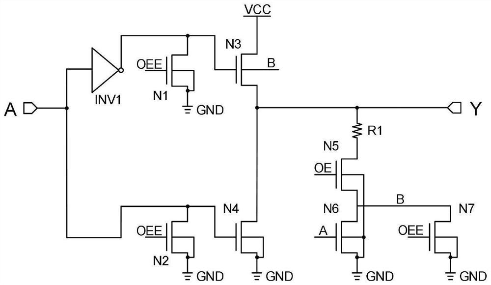
[0015] The present invention provides a hot-swap structure based on NMOS pull-up driver, its structure is as follows figure 1 As shown, it includes input terminal A, output terminal Y, NMOS transistors N1~N7, inverter INV1 and resistor R1; input terminal A is connected to the input terminal of inverter INV1, and the output terminal of the inverter INV1 is connected to NMOS at the same time The drain terminal of the tube N1 and the gate terminal of the NMOS tube N3; the drain terminal of the NMOS tube N3 is connected to the power supply VCC, and the source terminal is connected to the drain terminal of the NMOS tube N4 and the output terminal Y;

[0016] The input terminal A is connected to the drain terminal of the NMOS transistor N2 and the gate terminal of the NMOS transistor N4, and the drain terminal of the NMOS transistor N4 is connected to the source terminal of the NMOS transistor N3 and the output terminal Y;

[0017] The output terminal Y is connected to one end of th...


PUM


Abstract

The invention discloses a hot plug structure based on an NMOS pull-up driver, and belongs to the field of integrated circuit I / O ports. An input end A is connected with an input end of a phase inverter INV1, and an output end of the phase inverter INV1 is simultaneously connected with a drain end of an NMOS transistor N1 and a gate end of an NMOS transistor N3; the drain end of the NMOS tube N3 is connected with a power supply VCC, and the source end of the NMOS tube N3 is connected with the drain end and the output end Y of the NMOS tube N4; the input end A is connected with the drain end of the NMOS tube N2 and the gate end of the NMOS tube N4, and the drain end of the NMOS tube N4 is connected with the source end and the output end Y of the NMOS tube N3; the output end Y is connected with one end of the resistor R1, the other end of the resistor R1 is connected with the drain end of the NMOS tube N5, the source end of the NMOS tube N5 is connected with the drain end of the NMOS tube N6 and the drain end of the NMOS tube N7 at the same time, and the drain ends of the NMOS tube N6 and the NMOS tube N7 serve as the substrate potential B of the NMOS tube N3. According to the invention, the isolation NMOS tube is used as the pull-up tube of the output stage, the port hot plug requirement of the driving stage can be realized through the substrate floating structure design of the NMOS, the pull-down driving capability of the output stage is enhanced, and in addition, the substrate bias effect of the pull-up NMOS tube is eliminated.

Description

technical field [0001] The invention relates to the technical field of integrated circuit I / O ports, in particular to a hot-swap structure based on an NMOS pull-up driver. Background technique [0002] With the rapid development of modern integrated circuit technology, more and more electronic products have entered our lives. In system-level application circuits, the buffer circuit connected to the bus is widely used, and the buffer circuit is often used as a function of level conversion or enhancing signal driving capability. In practical applications of large-scale communication circuit systems, these buffer circuits often choose to enter a sleep or power-off mode in consideration of actual work requirements. In another special case, when the buffer circuit is damaged and needs to be replaced, the system circuit is often not allowed to be powered off. This requires the buffer circuit to be plug-and-play. Therefore, the buffer circuit is required to have a hot-swappable ...

Claims


Application Information

Patent Timeline
IPC IPC(8): H03K19/0185
CPCH03K19/018507Y02D10/00
Inventor 喻丹高国平于群
Owner 58TH RES INST OF CETC
Learn More