Frequency divider including latch circuits and method

A latching circuit and frequency divider technology, applied in electrical components, generating electrical pulses, synchronizing pulse counters, etc., can solve problems such as the performance limitation of the latching circuit 200, and achieve elimination of parasitic capacitance, improved performance, and high output voltage amplitude. Effect

Active Publication Date: 2008-12-10
凹凸科技平潭有限公司
View PDF0 Cites 5 Cited by
  • Summary
  • Abstract
  • Description
  • Claims
  • Application Information

AI Technical Summary

Problems solved by technology

Due to the parasitic capacitance introduced by the isolated NMOS transistor 500, the performance of the latch circuit 200 containing the isolated NMOS transistor 500 will be greatly limited

Method used


Image

  • Frequency divider including latch circuits and method
  • Frequency divider including latch circuits and method
  • Frequency divider including latch circuits and method

Examples


Embodiment Construction

[0031] A detailed description will be given below of embodiments of the present invention. While the invention will be described in conjunction with examples, it will be understood that it is not intended to limit the invention to these examples. On the contrary, the invention is intended to cover various alternatives, modifications and equivalents as defined within the spirit and scope of the invention as defined by the appended claims.

[0032] Furthermore, in the following detailed description of the invention, numerous specific details are set forth in order to provide a thorough understanding of the invention. However, it will be understood by those skilled in the art that the present invention may be practiced without these specific details. In some other embodiments, well-known schemes, processes, components and circuits are not described in detail, so as to highlight the gist of the present invention.

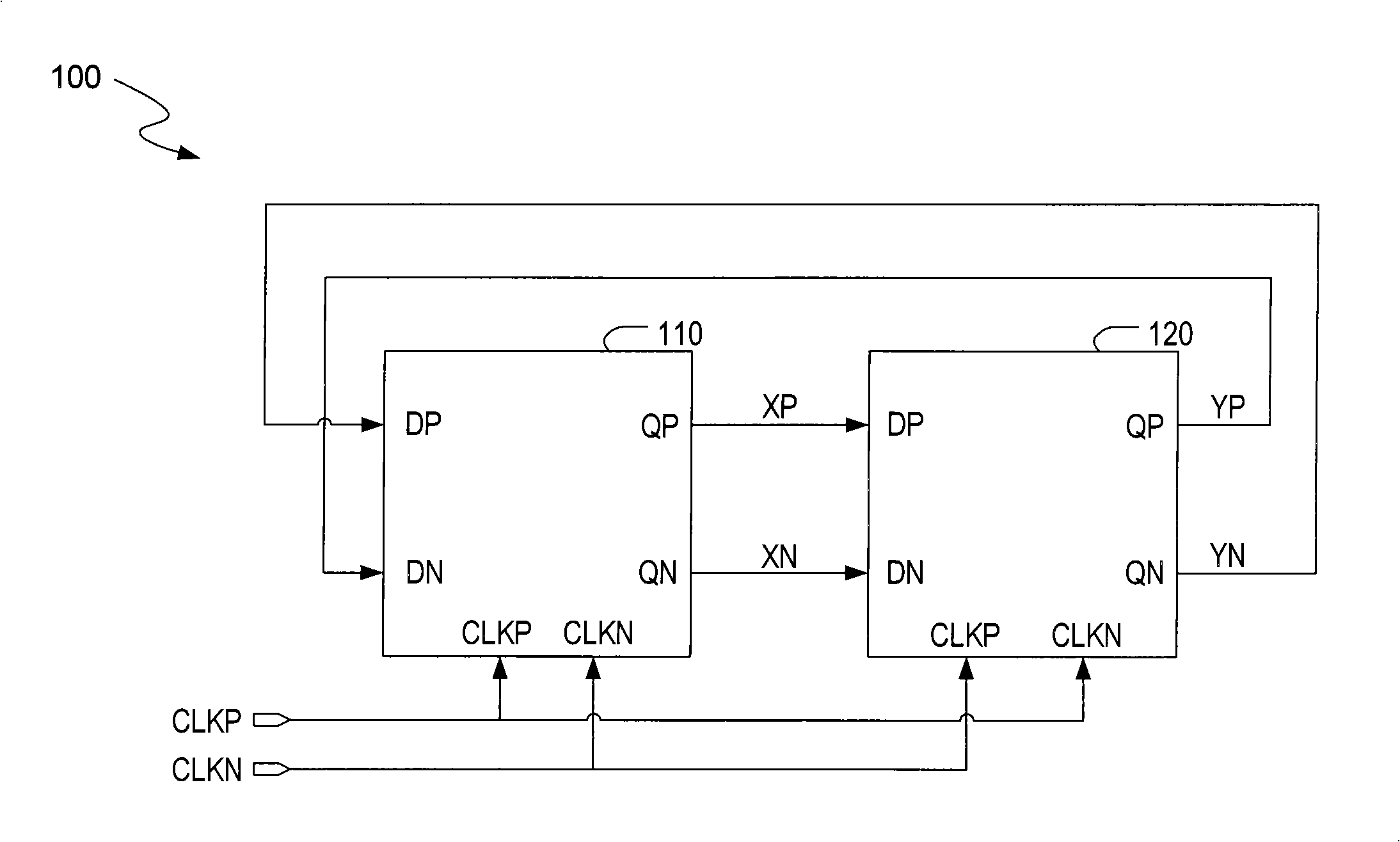
[0033] Figure 6 Shown is a block diagram of a latch circuit 60...


PUM


Abstract

A frequency divider is disclosed herein. The frequency divider includes a first latch circuit and a second latch circuit coupled to the first latch circuit. Each of the first latch circuit and the second latch circuit includes a first level for generating a source current, a second level for receiving a pair of input signals and for generating a pair of output signals, and a third level for receiving the source current and a pair of clock signals. The second level is coupled between the first level and the third level. The first level includes a first transistor having a source terminal and a substrate both coupled to a source voltage. The third level includes a plurality of transistors controlled by the pair of clock signals. Each transistor in the third level has a source terminal and a substrate both coupled to ground. Compared with current technique, the frequency divider provided in the invention removes transistor bias effect and parasitic capacitance, with the input signal having smaller value capable of conducting the input level thereof, which is capable of provided with relatively high output voltage amplitude free of buffer so as to enhance property thereof.

Description

technical field [0001] The present invention relates to frequency dividers, and more particularly to frequency dividers including latch circuits. Background technique [0002] Currently, with the rapid development of related technologies, the demand for high-performance electronic circuits is increasing. Therefore, frequency dividers (eg, divide-by-two circuits) are widely used in electronic circuits to meet the needs of different fields (eg, Global Positioning System (GPS) receivers, Code Division Multiple Access (CDMA) transceivers, etc.). [0003] figure 1 A block diagram of a conventional divide-by-two circuit 100 is shown. The divide-by-two circuit 100 uses two identical latch circuits (eg, latch circuits 110 and 120 ). The output of one latch circuit is passed to the input of the other latch circuit and vice versa. Each latch circuit is controlled by a pair of complementary clock signals CLKP and CLKN, and has a pair of input terminals (DP and DN) and a pair of out...

Claims


Application Information

Patent Timeline
IPC IPC(8): H03K23/42H03K23/44
CPCH03K3/011H03K3/356139
Inventor 褚蒙陈斯德
Owner 凹凸科技平潭有限公司
Why Eureka
Try Eureka