Supercharge Your Innovation With Domain-Expert AI Agents!

Electric connector and electric connector combination

A technology of electrical connectors and docking connectors, which is applied in the direction of connection, two-part connection devices, parts of connection devices, etc., can solve the complex structure of plug connectors and socket connectors, high product precision requirements, plug There are many problems with the mating structure of the connector and the socket connector

Inactive Publication Date: 2022-02-11
DEYI PRECISION ELECTRONIC IND CO LTD PANYU
View PDF1 Cites 0 Cited by
  • Summary
  • Abstract
  • Description
  • Claims
  • Application Information

AI Technical Summary

Problems solved by technology

[0004] 1. The mating structures of the socket connector and the plug connector are respectively arranged on the insulating body, which makes the molding process of the insulating body complicated and requires high product precision, which increases the production cost
[0005] 2. The structure of the plug connector and the socket connector for mutual cooperation is provided with an auxiliary structure and two main structures, which complicates the structure of the plug connector and the socket connector, and due to the gap between the plug connector and the socket connector There are many matching structures, which is not conducive to the miniaturization of plug connectors and socket connectors

Method used


Image

  • Electric connector and electric connector combination
  • Electric connector and electric connector combination
  • Electric connector and electric connector combination

Examples


Embodiment Construction

[0034] In order to facilitate a better understanding of the purpose, structure, features, and effects of the present invention, the present invention will now be further described in conjunction with the accompanying drawings and specific embodiments.

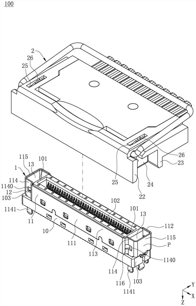
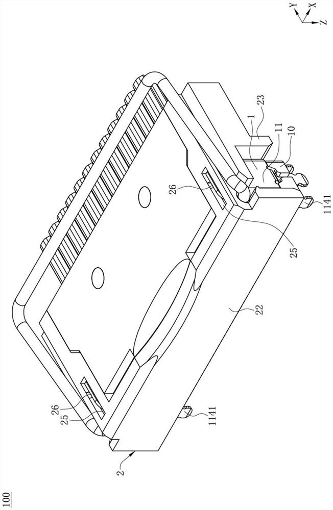
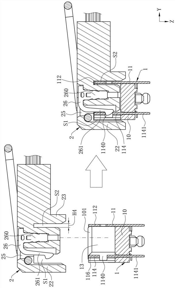
[0035] As shown, the electrical connector assembly 100 of the present invention defines the first direction as the X axis, the second direction as the Y axis, and the third direction as the Z axis.

[0036] Such as Figure 1 to Figure 9 As shown, it is the best embodiment of the electrical connector assembly 100 of the present invention. The electrical connector assembly 100 includes an electrical connector 1 and a butt joint mated with the electrical connector 1 along the third direction. Connector 2, in this embodiment, the first direction is the longitudinal direction, and the third direction is the up-and-down direction. The first direction and the third direction will be unified for explanation below, but in this embodimen...


PUM


Abstract

An electric connector combination comprises an electric connector, the electric connector comprises an insulation body with an inserting groove and a metal shell wrapping the insulation body, the metal shell comprises a shielding part and two matching parts arranged at the two sides of the shielding part in the first direction, and the matching parts are recessed from one side to the other side in the second direction perpendicular to the first direction to form a receding space; a butt joint connector is connected with the electric connector in an inserted mode and comprises fool-proof parts arranged in the two sides of the butt joint connector in the first direction, and the projections of the two fool-proof parts in the first direction coincide; in the second direction, a first plate part and a second plate part are arranged at the two sides of the butt joint connector, the fool-proof part is located between the first plate part and the second plate part, a first gap and a second gap are formed between the fool-proof part and the first plate part and between the fool-proof part and the second plate part, and the width of the first gap is larger than that of the second gap; and the butt joint connector is inserted into the electric connector, the first plate part and the second plate part are located in the two outer sides of the shielding part in the second direction, the fool-proof part is contained in the matching parts, and the receding space coincides with the first gap.

Description

【Technical field】 [0001] The invention relates to an electrical connector and an electrical connector combination, in particular to an electrical connector and an electrical connector combination that can not only reduce production costs and structural complexity, but also optimize the alignment structure of the connector. 【Background technique】 [0002] The patent with the Chinese application number CN201820350321.8 discloses an improved connector combination, the connector combination includes a plug connector and a socket connector mated with each other, wherein the insulating body of the socket connector includes a plurality of boards, The multiple boards include an auxiliary mating structure and two main mating structures, wherein the auxiliary mating structure and the two main mating structures respectively correspond to an auxiliary mating part and an insulating body provided with the plug connector. The two main fittings mate for mating. [0003] In the above struct...

Claims


Application Information

Patent Timeline
IPC IPC(8): H01R24/00H01R13/64H01R13/46H01R13/639
CPCH01R13/64H01R13/40H01R13/502H01R13/516
Inventor 陆元成莫兴建
Owner DEYI PRECISION ELECTRONIC IND CO LTD PANYU
Features
  • R&D
  • Intellectual Property
  • Life Sciences
  • Materials
  • Tech Scout
  • Unparalleled Data Quality
  • Higher Quality Content
  • 60% Fewer Hallucinations
Learn More