Forage throwing mechanism and stalk and spike harvesting type corn harvester

A forage and a pair technology, which is applied to the field of forage throwing mechanism and corn harvester with both stem and ear, can solve the problems of short length of the secondary throwing part, the forage falling on the ground, the lack of tacit coordination, etc., and the structure is simple. The effect of optimization, switching convenience, and reducing the requirement of the following distance

Pending Publication Date: 2022-02-15
河北英虎农业机械股份有限公司
View PDF0 Cites 0 Cited by
  • Summary
  • Abstract
  • Description
  • Claims
  • Application Information

AI Technical Summary

Problems solved by technology

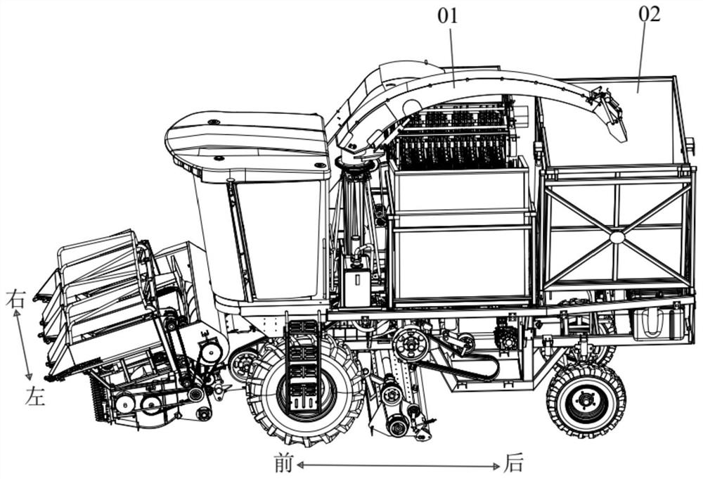
[0003] The secondary throwing part of the existing stem and ear harvesting type corn harvester can throw forage to the accompanying vehicle behind the side or to the forage bin on the corn harvester (such as figure 1 shown), but in order to align the secondary throwing part 01 with the forage bin 02, the length of the secondary throwing part is designed to be short, and the accompanying grass harvesting vehicle needs to only follow the corn harvester. The driver has high requirements, and it is easy to cause the forage to fall on the ground due to lack of cooperation

Method used


Image

  • Forage throwing mechanism and stalk and spike harvesting type corn harvester
  • Forage throwing mechanism and stalk and spike harvesting type corn harvester
  • Forage throwing mechanism and stalk and spike harvesting type corn harvester

Examples


Embodiment Construction

[0036] In order to make the purpose, technical solutions and advantages of the embodiments of the present invention clearer, the technical solutions in the embodiments of the present invention will be clearly and completely described below in conjunction with the drawings in the embodiments of the present invention. Obviously, the described embodiments It is a part of embodiments of the present invention, but not all embodiments. The components of the embodiments of the invention generally described and illustrated in the figures herein may be arranged and designed in a variety of different configurations.

[0037] Accordingly, the following detailed description of the embodiments of the invention provided in the accompanying drawings is not intended to limit the scope of the claimed invention, but merely represents selected embodiments of the invention. Based on the embodiments of the present invention, all other embodiments obtained by persons of ordinary skill in the art wi...


PUM


Abstract

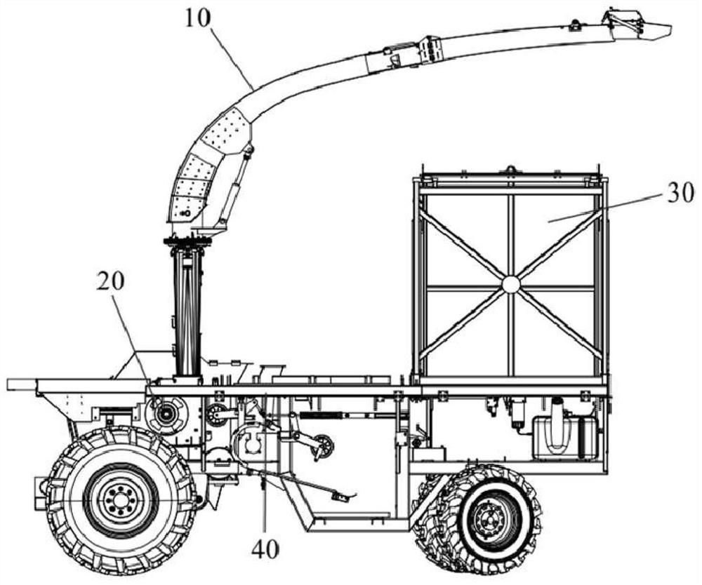
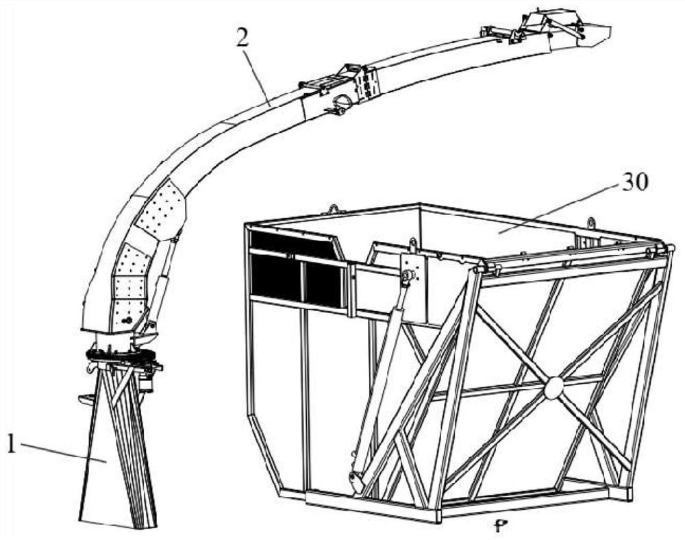
The invention discloses a forage throwing mechanism. The forage throwing mechanism comprises a vertical throwing part and an arc-shaped throwing part which are connected in sequence; the arc-shaped throwing part comprises a central sleeve, an arc-shaped spraying barrel and a spraying barrel cap which are connected in sequence; the arc-shaped spraying barrel comprises a basic spraying barrel and a lengthened spraying barrel, one end of the basic spraying barrel is installed at the upper end of the central sleeve in a hinged mode, and the lengthened spraying barrel is connected with the other end of the basic spraying barrel in a hinged mode; the end, close to the lengthened spraying barrel, of the basic spraying barrel is a passing opening, a forage guide plate is arranged at the passing opening, and when the forage throwing mechanism throws forage to the accompanying vehicle, the forage guide plate does not block the passing opening; when the forage throwing mechanism throws the forage to the forage bin, the forage guide plate blocks the passing opening. The working modes of the forage guide plate are convenient to switch, and after the lengthened spraying barrel is additionally arranged on the arc-shaped throwing part, the good effect that hay can be selectively sprayed to a forage bin or an accompanying truck can be achieved.

Description

technical field [0001] The invention relates to the field of corn harvesters, in particular to a forage throwing mechanism and a stem and ear harvester corn harvester. Background technique [0002] The corn harvester with both stems and ears generally includes a corn harvesting system, a straw harvesting system and a field returning machine. The corn harvesting system includes an upper header, a large elevator, a peeling machine and a granary. The upper header is used to pick corn ears. Next, the picked ears are transported to the peeling machine by the large elevator, and the peeling machine peels the ears, and the peeled ears are transported to the granary; the straw harvesting system includes the lower header, feeding device, crusher, throwing fan and two The secondary throwing section and the lower cutting platform are used to cut the straw from the root. The cut straw is transported to the crusher through the feeding device. The crusher chops the straw and throws the fo...

Claims


Application Information

Patent Timeline
Patent Type & Authority Applications(China)
IPC IPC(8): A01D43/08A01D45/02
CPCA01D43/086A01D45/021
Inventor 李衡李侠杨香林
Owner 河北英虎农业机械股份有限公司
Why Eureka
Try Eureka