Crane lifting adjusting device

An adjustment device and crane technology, which is applied in the direction of cranes, mechanical equipment, load blocks, etc., can solve problems such as prone to topping, large operating range, and lack of vibration reduction, so as to improve work efficiency, prevent excessive swing, and improve practicality. sexual effect

Active Publication Date: 2022-02-18
新乡市起重设备厂有限责任公司
View PDF17 Cites 2 Cited by
  • Summary
  • Abstract
  • Description
  • Claims
  • Application Information

AI Technical Summary

Problems solved by technology

According to its function and structural characteristics, cranes can be divided into four categories: light and small lifting equipment, bridge type cranes, jib type cranes, and elevators; cranes can reduce labor force and improve operating efficiency, and are widely used in various industries , with the development of the lifting industry, people have higher requirements for the safety, adjustability, and lifting capacity of the crane. The bridge crane relies on the lifting trolley to run on the track on the bridge frame to form a rectangular work. When lifting, the adjustment of the position of the hook is completely dependent on the adjustment of the lifting trolley and the beam. The control accuracy of the lifting trolley is not high, and the operating range is large. It is difficult to control the position of the hook. It is inconvenient to operate when the hook is connected to the cargo. Moreover, it cannot be rotated, and the efficiency of lifting goods is low. When the limit device of the crane fails, it is easy to rush to the top, and there is a certain danger. functions, are prone to failure, and cannot meet the needs of actual use, so there is an urgent need for improved technology in the market to solve the above problems

Method used


Image

  • Crane lifting adjusting device
  • Crane lifting adjusting device
  • Crane lifting adjusting device

Examples


Embodiment 1

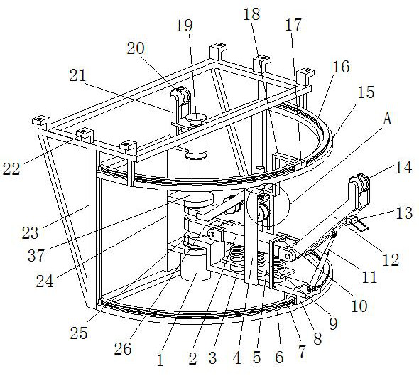
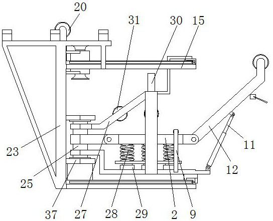
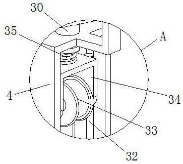
[0026] see Figure 1-5, the present invention provides a technical solution: a hoisting adjustment device for a crane, including a vibration damping arm 2, a rotating support arm 3, a hoisting adjustment arm 12, a lifting rope limit sleeve 19, a mounting frame 23 and a rotating fixed frame 24, rotating Fixing frame 24 is arranged on mounting frame 23, and the front and rear sides of mounting frame 23 tops are all provided with installation suspension plate 22, and installation suspension plate 22 is provided with installation hole, facilitates this device to be installed on the trolley by installing suspension plate 22 Below, the rotating fixed frame 24 is provided with a rotating shaft 25, and the right side of the rotating fixed frame 24 is provided with an ear plate 37. There are two ear plates 37, and the rotating shaft 25 is arranged between the ear plates 37. The lower ear plate The plate 37 is provided with a motor 1, the output shaft of the motor 1 is connected with th...


PUM


Abstract

The invention discloses a crane lifting adjusting device, which comprises a vibration reduction arm, a rotary supporting arm, a lifting adjusting arm, a lifting rope limiting bush, a mounting frame and a rotary fixing frame, wherein the rotary fixing frame is arranged on the mounting frame, a rotary shaft is arranged on the rotary fixing frame, a connecting arm is arranged in the middle of the rotary shaft, the left end of the vibration reduction arm is rotationally connected with the connecting arm, the left end of the lifting adjusting arm is rotationally connected with the vibration reduction arm, the rotary supporting arm is arranged under the vibration reduction arm, the left end of the rotary supporting arm is fixedly connected with the rotary shaft, a weight detection table is arranged between the rotary supporting arm and the vibration reduction arm, and a weight sensor is arranged between the weight detection table and the rotary supporting arm. According to the invention, the crane lifting adjusting device is novel in structural design, double protection is conducted on lifting equipment, goods are prevented from rushing to the top, safe operation of lifting work is guaranteed, operation is convenient, the working efficiency is greatly improved, the position of the lifting hook can be finely adjusted, and the practicability of the lifting device is improved.

Description

technical field [0001] The invention relates to the technical field of crane hoisting, in particular to a crane hoisting adjustment device. Background technique [0002] A crane refers to a multi-action hoisting machine that lifts vertically and carries heavy objects horizontally within a certain range. According to its function and structural characteristics, cranes can be divided into four categories: light and small lifting equipment, bridge type cranes, jib type cranes, and elevators; cranes can reduce labor force and improve operating efficiency, and are widely used in all walks of life , with the development of the lifting industry, people have higher requirements for the safety, adjustability, and lifting capacity of the crane. The bridge crane relies on the lifting trolley to run on the track on the bridge frame to form a rectangular work. When lifting, the adjustment of the position of the hook is completely dependent on the adjustment of the lifting trolley and th...

Claims


Application Information

Patent Timeline
Patent Type & Authority Applications(China)
IPC IPC(8): B66C11/10B66C11/16B66C23/06B66C13/16B66C23/82B66C23/88B66C23/84B66C13/08F16F15/067
CPCB66C11/10B66C11/16B66C23/06B66C13/16B66C23/826B66C23/88B66C23/84B66C13/08F16F15/067
Inventor 钮玉景甘欢庆杨慧芳闫晓妮姬予宁王丽丽
Owner 新乡市起重设备厂有限责任公司
Why Eureka
Try Eureka