Molding equipment for gum soft board

A molding equipment and soft board technology, applied in the field of rubber soft board molding equipment, can solve the problems of slow production speed and the like

Pending Publication Date: 2022-03-08
徐娟
View PDF0 Cites 0 Cited by
  • Summary
  • Abstract
  • Description
  • Claims
  • Application Information

AI Technical Summary

Problems solved by technology

[0005] In order to overcome the shortcomings of slow production speed and the need to manually take out the rubber soft board from the mold, the technical problem is to provide a rubber soft board molding that can automatically blank the mold and automatically take out the formed rubber soft board equipment

Method used


Image

  • Molding equipment for gum soft board
  • Molding equipment for gum soft board
  • Molding equipment for gum soft board

Examples


Embodiment 1

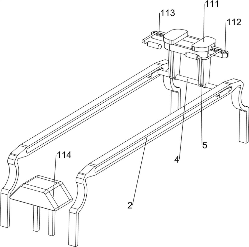
[0029] A kind of gum soft board forming equipment, such as Figure 1-2 As shown, it includes a base plate 1, a first slide rail 2, a slider 3, a first rotating shaft 4, a mold 5, a moving mechanism 6 and a blanking mechanism 7, and the upper part of the base plate 1 is symmetrically provided with the first slide rail 2, and the second Slide rails 2 are provided with sliders 3 for sliding, and a first shaft 4 is provided for rotation between the sliders 3. A mold 5 is provided on the first shaft 4. A moving mechanism 6 is provided on the upper part of the base plate 1. The upper part of the base plate 1 A blanking mechanism 7 is provided in the middle.

[0030] When the user needs to make and shape the rubber material, he can use this equipment. Firstly, the rubber material is placed in the unloading mechanism 7, and the moving mechanism 6 drives the slider 3, the first rotating shaft 4 and the mold 5 to move to the left and close to the bottom. The position of the feeding mec...

Embodiment 2

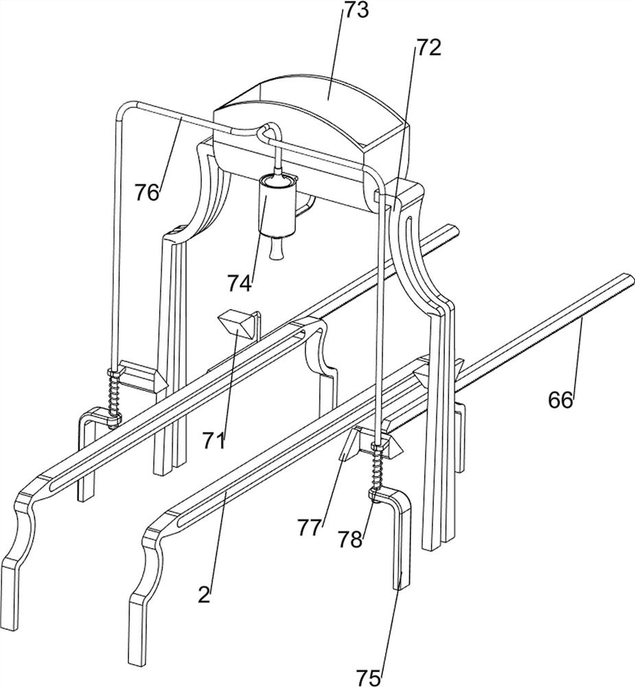
[0032] On the basis of Example 1, such as Figure 3-4 As shown, the moving mechanism 6 includes a motor 61, a first bracket 62, a second rotating shaft 63, a first full gear 64, a first belt 65 and a first rack 66, and the middle of the upper front side of the base plate 1 is provided with a motor 61, and the base plate 1 Two first brackets 62 are arranged on the front side of the upper part, and a second rotating shaft 63 is arranged in rotation between the first brackets 62, and a first full gear 64 is arranged on the second rotating shaft 63, and the output of the second rotating shaft 63 and the motor 61 A first belt 65 is connected between the shafts, and a first rack 66 is connected to the slider 3 , and the first rack 66 meshes with the first full gear 64 .

[0033] Start the motor 61, the motor 61 drives the first full gear 64 to mesh, and the first rack 66 meshes with the first full gear 64, so that the first rack 66 drives the slider 3 and the mold 5 to move to the l...

Embodiment 3

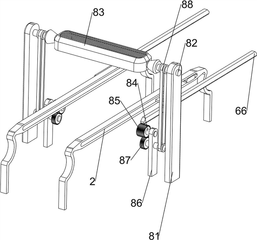
[0037] On the basis of Example 2, such as Figure 5-8As shown, a drying mechanism 8 is also included, and the drying mechanism 8 includes a second support frame 81, a third rotating shaft 82, a heater 83, a fourth rotating shaft 84, a second full gear 85, a third bracket 86, a third All gears 87 and the second belt 88, a second support frame 81 is arranged symmetrically front and back in the middle of the upper part of the bottom plate 1, a third rotating shaft 82 is arranged in a rotating manner between the second supporting frame 81, and a heater 83 is arranged on the third rotating shaft 82 , the upper middle of the bottom plate 1 is provided with a third support 86 symmetrically front and back, the third support 86 is provided with a fourth rotating shaft 84, the fourth rotating shaft 84 on the upper side is provided with a second full gear 85, and the fourth rotating shaft 84 on the lower side is provided with a second full gear 85. The third full gear 87 is provided on t...


PUM


Abstract

The invention relates to forming equipment, in particular to gum soft board forming equipment. The technical problem is to provide the gum soft board forming equipment capable of automatically blanking a mold and automatically taking out a formed gum soft board. The invention discloses gum soft board forming equipment which comprises a bottom plate, a bottom plate and a bottom plate, the first sliding rails are symmetrically arranged at the upper part of the bottom plate; the sliding blocks are arranged on the first sliding rails in a sliding manner; the first rotating shaft is rotationally arranged between the sliding blocks; and the mold is arranged on the first rotating shaft. The effects that the die can be automatically blanked, and the formed rubber soft plate is automatically taken out are achieved; the fixing blocks abut against the sliding blocks, so that the sliding blocks move towards the two sides, and the rubber soft plate in the mold falls out towards the outer side.

Description

technical field [0001] The invention relates to a molding device, in particular to a rubber soft board molding device. Background technique [0002] Silicone sleeves are generally made of rubber, soft and elastic, and are often used to protect digital products from accidental drops or abrasions. [0003] When people make rubber molds, they generally place rubber raw materials in the mold, wait for the rubber in the mold to form, and then take out the rubber soft plate formed in the mold. This way of making rubber soft plates makes the production speed slower. And it is necessary to manually take out the soft rubber plate in the mould. [0004] Therefore, it is necessary to design a rubber soft board molding equipment that can automatically blank the mold and automatically take out the formed rubber soft board. Contents of the invention [0005] In order to overcome the shortcomings of slow production speed and the need to manually take out the rubber soft board from the ...

Claims


Application Information

Patent Timeline
IPC IPC(8): B29C39/02B29C39/24B29C39/36
CPCB29C39/02B29C39/24B29C39/36
Inventor 徐娟
Owner 徐娟
Why Eureka
Try Eureka