
Drainage device for abdominal cavity high pressure patient

A high-pressure, patient-friendly technology, applied in the direction of suction devices, catheters, etc., can solve problems such as stimulation, high negative pressure, and large suction of drainage tubes

Pending Publication Date: 2022-03-15
中国人民解放军陆军特色医学中心
View PDF6 Cites 0 Cited by
  • Summary
  • Abstract
  • Description
  • Claims
  • Application Information

AI Technical Summary

Problems solved by technology

Since the peritoneal drainage tube is usually directly inserted into the patient's abdominal cavity from the wound of the patient's abdominal cavity, it is inevitable that the abdominal drainage tube will shake and rub against the wound skin of the patient's abdomen during use, so that the abdominal drainage tube will stimulate the patient's wound Moreover, when using the negative pressure drainage device to drain the patient's abdominal cavity through the abdominal cavity drainage tube, the medical staff usually directly pinch the drainage tube to achieve the purpose of suspending the drainage. Since the negative pressure drainage device is always working, the drainage tube The negative pressure in the end close to the negative pressure drainage device is relatively high, so that when the medical staff loosen the drainage tube, the drainage tube will generate a large suction momentarily, which will affect the adsorption effect of the drainage tube, and at the same time, it will easily make the tissue of the patient's abdominal cavity sucked by the drainage tube

Method used


Image

  • Drainage device for abdominal cavity high pressure patient
  • Drainage device for abdominal cavity high pressure patient
  • Drainage device for abdominal cavity high pressure patient

Examples


Embodiment Construction

[0026] The following will clearly and completely describe the technical solutions in the embodiments of the present invention with reference to the accompanying drawings in the embodiments of the present invention. Obviously, the described embodiments are only some, not all, embodiments of the present invention. Based on the embodiments of the present invention, all other embodiments obtained by persons of ordinary skill in the art without making creative efforts belong to the protection scope of the present invention.

[0027] In the description of the present invention, it should be understood that the orientations or positional relationships indicated by the terms "top", "bottom", "inner", "outer", "first", "last" etc. are based on those shown in the accompanying drawings. Orientation or positional relationship is only for the convenience of describing the present invention and simplifying the description, and does not indicate or imply that the referred device or element mu...


PUM


Abstract

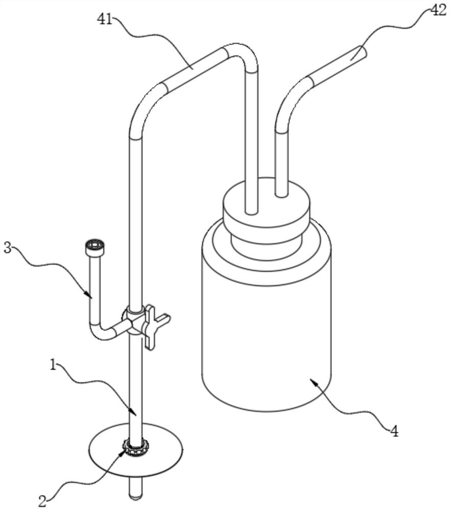
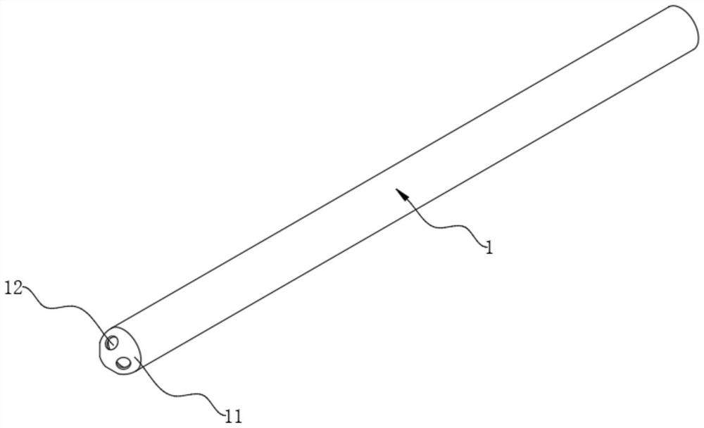
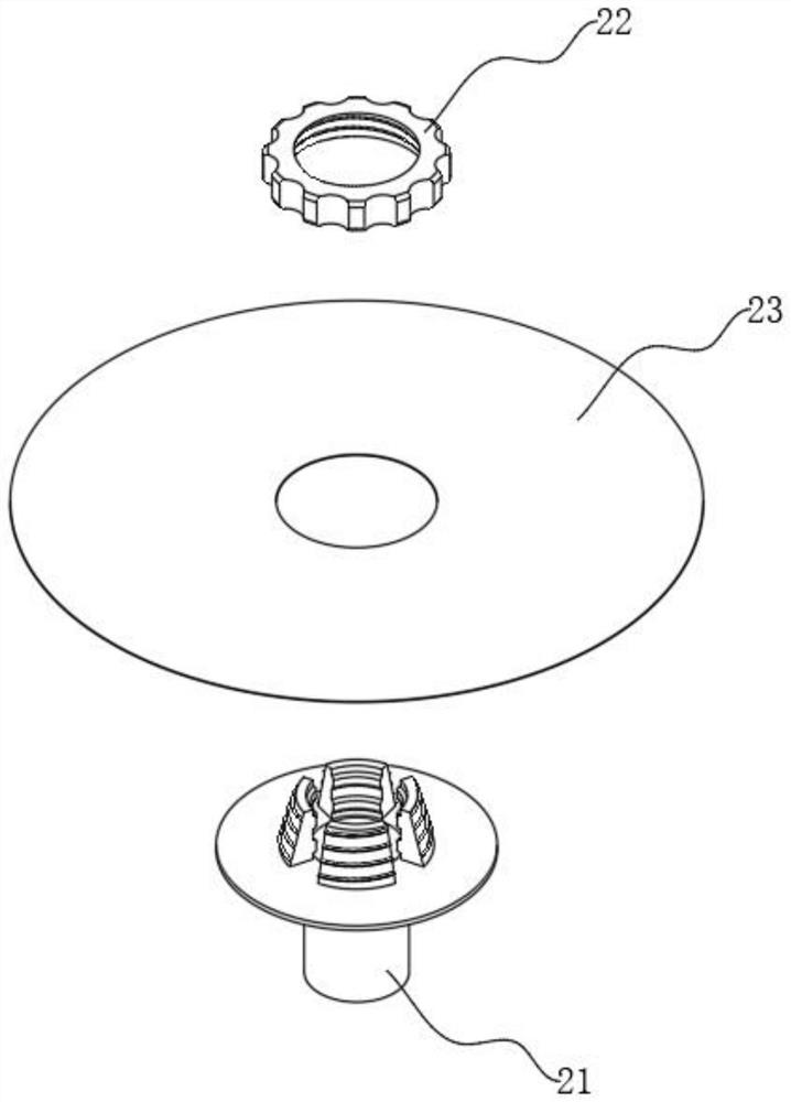
The invention relates to the technical field of peritoneal drainage instruments, in particular to a drainage device for a patient suffering from peritoneal hypertension, which comprises a drainage tube main body, a fixator is sleeved on the outer side of the bottom end of the drainage tube main body, the fixator comprises a sleeve, a screwing sleeve and an adhesive tape, the top end of the drainage tube main body is communicated with a connecting tube through a three-way valve, and the three-way valve is further communicated with a branch tube. The end, away from the drainage tube body, of the connecting tube is connected with a suction bottle, and a negative pressure tube is inserted into the suction bottle. The drainage tube is fixed to an abdominal wound through the fixator, the bottom end of the drainage tube body penetrates through the fixator to be inserted into the abdominal wound of a patient, negative pressure is generated in the drainage tube body through negative pressure suction equipment, and therefore liquid in the abdominal cavity of the patient can be sucked by the drainage tube body and then enters a suction bottle; by controlling the three-way valve, the connecting tube and the drainage tube main body can be communicated or closed, and the situation that the suction force of the drainage tube main body is too large due to too large negative pressure when the drainage tube main body is communicated again is prevented.

Description

technical field [0001] The invention relates to the technical field of abdominal drainage devices, in particular to a drainage device for patients with abdominal hypertension. Background technique [0002] After performing abdominal surgery on patients with abdominal hypertension, a peritoneal drainage tube is usually installed on the patient to drain the bleeding, exudate and other drainage fluid in the wound or incision, and observe the bleeding and exudate in the abdominal cavity to judge the status of the incision after the operation , the patient's recovery, etc., and the abdominal drainage tube can be used to clean the patient's abdominal cavity to play a therapeutic role. Since the peritoneal drainage tube is usually directly inserted into the patient's abdominal cavity from the wound of the patient's abdominal cavity, it is inevitable that the abdominal drainage tube will shake and rub against the wound skin of the patient's abdomen during use, so that the abdominal ...

Claims


Application Information

Patent Timeline
Patent Type & Authority Applications(China)
IPC IPC(8): A61M1/00A61M25/02
CPCA61M25/02A61M2025/0253
Inventor 唐昊王耀丽张连阳
Owner 中国人民解放军陆军特色医学中心
Learn More