New energy lithium battery puncturing equipment

A lithium battery and new energy technology, applied in the field of new energy lithium battery puncture equipment, can solve the problems of easy harm and trouble to people, and achieve the effect of avoiding damage from explosions

Inactive Publication Date: 2022-03-22
黄敏
View PDF1 Cites 4 Cited by
  • Summary
  • Abstract
  • Description
  • Claims
  • Application Information

AI Technical Summary

Problems solved by technology

[0005] In order to overcome the shortcomings of the above-mentioned patents that manual operation is still required to puncture the new energy lithium battery, which is cumbersome, and it is easy to cause harm to people in the event of an explosion, the present invention provides a method that can replace manual puncture testing of the new energy lithium battery. It is a new energy lithium battery puncture device that is more convenient and avoids people being injured by explosions

Method used


Image

  • New energy lithium battery puncturing equipment
  • New energy lithium battery puncturing equipment
  • New energy lithium battery puncturing equipment

Examples


Embodiment 1

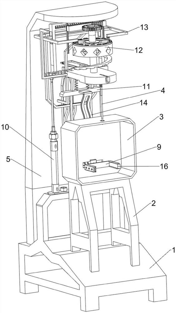
[0038] A new energy lithium battery puncture device, including a base 1, a support frame 2, a frame body 3, a steel needle 4, an L-shaped plate 5, an L-shaped clamp plate 6, a fixing block 7, a torsion spring 8, a placement mechanism 9 and a drive Institution 10, see Figure 1-Figure 7 As shown, an L-shaped plate 5 is installed in the middle of the top rear side of the base 1 by welding, and a fixed block 7 is installed on the front side of the top middle of the base 1 by welding, and the upper left and right sides of the fixed block 7 are rotated An L-shaped clamping plate 6 is connected, and a torsion spring 8 is connected between the lower part of the left and right sides of the L-shaped clamping plate 6 and the inner, left and right sides of the fixed block 7 respectively. The frame 3 is installed on the top by welding, and the lower part of the rear side of the frame 3 is equipped with a placement mechanism 9. The operator can place the new energy lithium battery on the p...

Embodiment 2

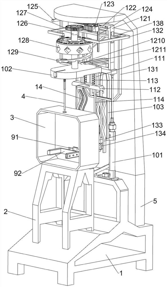
[0045] On the basis of Embodiment 1, an adjustment mechanism 11 is also included. The adjustment mechanism 11 includes an n-type plate 111, a guide rail 112, a first spring 113, a missing rack 114, a second spring 115 and a limit plate 116. Please refer to figure 1 , figure 2 , image 3 and Figure 10 As shown, an n-type plate 111 is slidingly connected in the middle of the rear of the movable plate 102, and a guide rail 112 is installed between the two ends of the bottom of the n-type plate 111 by welding, and the outer top of the guide rail 112 is connected to the rear side of the movable plate 102 bottom. The first spring 113 is symmetrically connected between the left and right, and there are two missing racks 114 slidingly placed in the guide rail 112. When the missing racks 114 move downward, the missing racks 114 can drive the column gear 94 to rotate, and the left and right two A second spring 115 is installed between the top of the outer surface of the side missing...

Embodiment 3

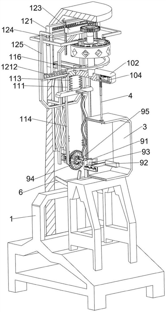
[0052] On the basis of Embodiment 1 and Embodiment 2, a wave guide plate 14 and a trigger lever 15 are also included, please refer to figure 1 , figure 2 , Figure 11 and Figure 12 As shown, a trigger lever 15 is installed in the left and right sides of the Liuling pole 93 through welding connection, and a wave guide plate 14 is installed in the middle of the outer front side of the guide rail 112 through welding. The trigger lever 15 is located in the wave guide plate 14. When When the wave guide plate 14 moves, the wave guide plate 14 can drive the trigger lever 15 to move back and forth.

[0053] Also include rubber plate 16, guide rod 17 and the seventh spring 18, please refer to figure 1 and Figure 14 As shown, the U-shaped plate 92 is evenly spaced on the left and right sides of the slide type and connected with three guide rods 17, and the inner ends of the three guide rods 17 on the left and the inner ends of the three guide rods 17 on the right are all connecte...


PUM


Abstract

The invention relates to puncture equipment, in particular to new energy lithium battery puncture equipment. A new energy lithium battery puncture device which can replace manual work to carry out a puncture test on a new energy lithium battery, is relatively convenient and also prevents people from being injured by explosion needs to be designed. New energy lithium battery puncturing equipment comprises a base, an L-shaped plate, a fixing block and the like, the L-shaped plate is fixedly connected to the middle of the rear side of the top of the base, and the fixing block is fixedly connected to the front side of the middle of the top of the base. The new energy lithium battery is placed on the placing mechanism, then the placing mechanism is pulled to operate to adjust the position and angle of the new energy lithium battery, the driving mechanism is started, the driving mechanism operates to drive the steel needle to move downwards, the steel needle moves downwards to make contact with the new energy lithium battery, and the steel needle conducts a puncture test on the new energy lithium battery. The puncture test of the new energy lithium battery can be carried out without manual operation, the operation is convenient, and the explosion damage can be avoided.

Description

technical field [0001] The invention relates to a puncture device, in particular to a new energy lithium battery puncture device. Background technique [0002] In the production process of new energy lithium batteries, it is necessary to carry out multiple tests on the produced new energy lithium batteries to complete the final treatment. The puncture test of new energy lithium batteries is essential, and the puncture test can be used for new energy lithium batteries. Battery safety is tested. [0003] The Chinese patent with the application number CN201920107909.5 discloses a battery puncture pressure measuring device. One end of the base is vertically provided with a baffle, the other end of the base is vertically provided with an elastic screw mounting plate, and the two ends of the clamping block are installed on the top of the base. and the clamping block can slide on the guide rail. The side of the clamping block facing the baffle is provided with a first arc-shaped t...

Claims


Application Information

Patent Timeline
Patent Type & Authority Applications(China)
IPC IPC(8): G01N19/00
CPCG01N19/00
Inventor 黄敏
Owner 黄敏
Why Eureka
Try Eureka