A flux fluid pressure control device

A fluid pressure and control device technology, applied in the field of welding processing, can solve the problems of flux bubble interference, poor welding quality, poor welding, etc., and achieve the effects of high stability, improved dissolution effect, and simple structure

Active Publication Date: 2022-04-26
FRD SCI & TECH (JIANGSU) CO LTD
View PDF15 Cites 0 Cited by
  • Summary
  • Abstract
  • Description
  • Claims
  • Application Information

AI Technical Summary

Problems solved by technology

Due to factors such as impurities or pipe bending, the flow of flux will be unstable, which will lead to poor welding and seriously affect the welding quality
[0003] The existing flux delivery pipeline structure mainly uses impeller pumps, plunger pumps or other mechanical pumps for direct supply and delivery. Due to various factors in the pipeline, it is easy to cause changes in the delivery pressure, resulting in fluctuations in the flux jet flow at the outlet. The flux jet cannot be precisely aimed at the welding surface, which affects the welding quality. In addition, in the process of flux pumping, the gas in the flux is often mixed, resulting in sputtering of the flux at the outlet and cannot be accurately supplied to the welding surface, and the existence of gas It mainly appears in the form of large bubbles. When the gas moves to the outlet section, the short-term supply of flux is suspended and the welding quality is affected. There are certain defects.
[0004] In view of this, the existing problems are studied and improved, and a flux fluid pressure control device is provided to solve the current problem of unstable flux delivery fluid pressure and poor soldering quality caused by interference of air bubbles inside the flux. Through this technology, the purpose of solving problems and improving practical value is achieved

Method used


Image

  • A flux fluid pressure control device
  • A flux fluid pressure control device
  • A flux fluid pressure control device

Examples


Embodiment Construction

[0036] In order to make the object, technical solution and advantages of the present invention clearer, the present invention will be further described in detail below in combination with specific embodiments and with reference to the accompanying drawings. It should be noted that, in the case of no conflict, the embodiments of the present invention and the features in the embodiments can be combined with each other.

[0037] It is understood that these descriptions are exemplary only, and are not intended to limit the scope of the invention.

[0038] A flux fluid pressure control device provided by some embodiments of the present invention is described below with reference to the accompanying drawings.

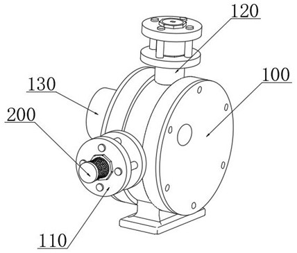
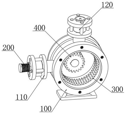
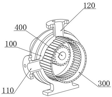
[0039] combine Figure 1-7As shown, a flux fluid pressure control device provided by the present invention includes: a pressure stabilizing pump box 100, a defoaming valve group 200, and an active conveying assembly 300. A conveying cavity 101 is provided inside the stabiliz...


PUM


Abstract

The invention discloses a welding flux fluid pressure control device, which comprises: a pressure stabilizing pump box, a defoaming valve group and an active conveying component. The interior of the stabilizing pump box is provided with a conveying cavity. The conveying cavity is connected to the inlet port and the outlet port. One side of the pressure-stabilizing pump box is fixedly installed with a drive motor, and the output end of the drive motor is fixedly sleeved with a drive tooth sleeve located inside the conveying cavity. In the present invention, by setting the active pressure compensation structure, the pressure-stabilizing pump box and the active conveying component are used to isolate and block the liquid flow movement at both ends to avoid the mutual influence of the pressure of the liquid flow at both ends, and the uniform motion of the drive motor utilizes the active The change of the cavity between the conveying component and the inner wall of the pressure-stabilizing pump box promotes the positive pressure of the liquid flow to keep the fluid pressure at the flux outlet end constant, and the pressure control can be realized by adjusting the power speed of the drive motor.

Description

technical field [0001] The invention relates to the technical field of welding processing, in particular to a flux fluid pressure control device. Background technique [0002] Welding, also known as welding or welding, is a manufacturing process and technology that uses heat, high temperature or high pressure to join metal or other thermoplastic materials such as plastics. In the soldering process, flux helps and facilitates the soldering process while protecting and preventing oxidation reactions. In the prior art, the supply of flux is based on the action of gravity and flows to the nozzle through the pipe, and then the flux is sprayed out from the nozzle. Due to factors such as impurities or pipe bending, the flux flow will be unstable, which will lead to poor welding and seriously affect the welding quality. [0003] The existing flux delivery pipeline structure mainly uses impeller pumps, plunger pumps or other mechanical pumps for direct supply and delivery. Due to v...

Claims


Application Information

Patent Timeline
Patent Type & Authority Patents(China)
IPC IPC(8): B23K3/08
CPCB23K3/082
Inventor 景佰亨肖珩潘洪明
Owner FRD SCI & TECH (JIANGSU) CO LTD
Why Eureka
Try Eureka