
A visual alarm method, device and system

A vision and sensor technology, applied to control devices and other directions, can solve problems such as incorrect use and abnormal alarms

Active Publication Date: 2022-05-03
北京鉴智科技有限公司
View PDF9 Cites 0 Cited by
  • Summary
  • Abstract
  • Description
  • Claims
  • Application Information

AI Technical Summary

Problems solved by technology

[0003] The purpose of this application is to provide a visual alarm method, device and system, so as to solve the problem of abnormal alarm caused by the alarm system in the prior art because it cannot correctly use the received data

Method used


Image

  • A visual alarm method, device and system
  • A visual alarm method, device and system
  • A visual alarm method, device and system

Examples


Embodiment Construction

[0042] The following will clearly and completely describe the technical solutions in the embodiments of the present application with reference to the drawings in the embodiments of the present application. Obviously, the described embodiments are part of the embodiments of the present application, not all of them. Based on the embodiments in this application, all other embodiments obtained by persons of ordinary skill in the art without creative efforts fall within the protection scope of this application.

[0043] The terms "first", "second" and the like in the specification and claims of the present application are used to distinguish similar objects, and are not used to describe a specific sequence or sequence. It is to be understood that the data so used are interchangeable under appropriate circumstances such that the embodiments of the application can be practiced in sequences other than those illustrated or described herein. In addition, "and / or" in the specification an...


PUM


Abstract

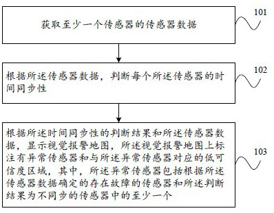
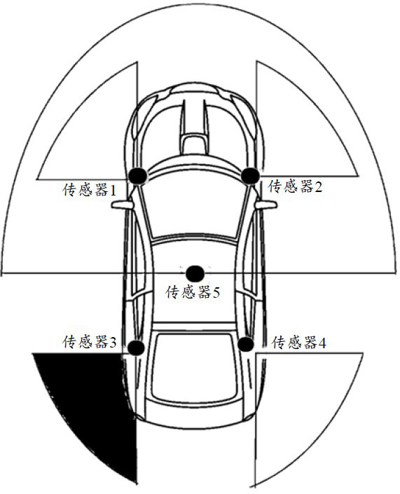
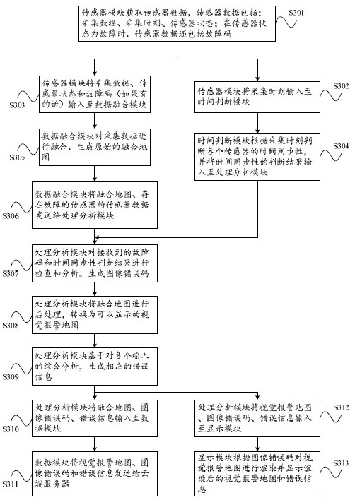
The present application discloses a visual alarm method, device and system, which relate to the technical field of automatic driving. The method includes: acquiring sensor data of at least one sensor; judging the time synchronization of each of the sensors according to the sensor data; According to the judgment result of the time synchronization and the sensor data, a visual alarm map is displayed, and an abnormal sensor and a low reliability area corresponding to the abnormal sensor are marked on the visual alarm map, wherein the abnormal sensor It includes at least one of a faulty sensor determined according to the sensor data and a sensor out of synchronization as a result of the determination. The scheme of the present application ensures the correct use of the acquired data by judging the time synchronization of the sensor. Based on the judgment result of the acquired time synchronization and sensor data, a visual alarm map is displayed, which realizes real-time alarm and can reserve more processing time.

Description

technical field [0001] The present application relates to the technical field of automatic driving, in particular to a visual warning method, device and system. Background technique [0002] The current alarm technology mostly focuses on the detection and correction of the input data collection process and preprocessing process. However, this method can only ensure the accuracy of the data input into the alarm system, but cannot ensure that the alarm system can use these data correctly, so , there will be abnormal alarms, such as untimely alarms, missed alarms, etc., resulting in potential safety hazards. Contents of the invention [0003] The purpose of the present application is to provide a visual alarm method, device and system, so as to solve the problem of abnormal alarm caused by the alarm system in the prior art that cannot correctly use the received data. [0004] In order to achieve the above purpose, the application provides a visual alarm method, including: ...

Claims


Application Information

Patent Timeline
Patent Type & Authority Patents(China)
IPC IPC(8): B60W50/14B60W50/02
CPCB60W50/14B60W50/0205B60W2050/146B60W2050/0215
Inventor 栾沁伦
Owner 北京鉴智科技有限公司
Learn More