Developing box

A developing cartridge and transmission component technology, which is applied in the developing cartridge field, can solve the problems of low yield, complex developing cartridge structure, high processing and manufacturing difficulty of the developing cartridge, etc., and achieves the effects of low processing and manufacturing difficulty, and simple realization method and structure.

Pending Publication Date: 2022-04-12
ZHUHAI YUANCHENG DIGITAL TECH CO LTD
View PDF1 Cites 0 Cited by
  • Summary
  • Abstract
  • Description
  • Claims
  • Application Information

AI Technical Summary

Problems solved by technology

[0006] In order to touch the contact rod 7A at different speeds, the above-mentioned detection gear requires precise cooperation of multiple parts, resulting in a complex structure of the development cartridge, especially the detection gear, which makes the processing and manufacturing of the development cartridge difficult and the yield of the product is low.

Method used


Image

  • Developing box
  • Developing box
  • Developing box

Examples


Embodiment Construction

[0035] Hereinafter, the structure and other aspects of the shadow cartridge of the present invention will be further described in detail through specific implementation methods and with reference to the accompanying drawings.

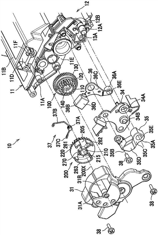
[0036] Figure 4 and Figure 5is a perspective view of the developing cartridge of the present invention according to the first embodiment. The developing cartridge of the present invention includes a housing 1, a transmission assembly 2, a rotatable member (not shown) and an end cover 3, wherein the housing 1 includes sidewalls 11 on both sides and formed inside for accommodating the rotatable member or carbon Powder (developer) cavity. The rotatable member includes, for example, a developing roller, a powder feeding roller, or a stirring frame, and the two ends of the rotatable member are rotatably mounted on the two side walls 11 of the casing 1 . The transmission assembly 2 is installed at one end of the housing 1 and is located between the side ...


PUM


Abstract

The invention relates to a developing box which comprises a shell, a transmission assembly and a counting mechanism, the transmission assembly and the counting mechanism are arranged at the end of the developing box, the transmission assembly receives driving force from an image forming device and drives the counting mechanism to work, and the transmission assembly comprises a power receiving part. The counting mechanism comprises a counting deflector rod, a horizontal push rod and a first actuating protrusion. Wherein the counting deflector rod is used for triggering a detection mechanism in the image forming device and is rotatably mounted on the developing box. And the horizontal pusher moves horizontally under the action of elastic force so as to push the counting deflector rod to rotate. The first actuating protrusion is used for triggering the horizontal push rod to enable the horizontal push rod to horizontally move under the action of elastic force and is arranged on the transmission assembly so as to be driven by the transmission assembly to rotate. Compared with the prior art, the developing box disclosed by the invention is simpler in implementation mode and structure and lower in processing and manufacturing difficulty under the condition of meeting the detection time sequence requirement of the image forming device.

Description

technical field [0001] The invention relates to a developing cartridge. In particular, it relates to a developing cartridge detachably mounted to a laser image forming apparatus. Background technique [0002] The developing cartridge is an essential printing consumable in the laser image forming device. After the laser image forming device works for a period of time, the toner filled in the developing box will be exhausted, and at this time a new developing box needs to be replaced. [0003] For some types of developer cartridges, the manufacturer usually sets a counting mechanism on the developer cartridge, which can be used in conjunction with the detection mechanism (sensor) on the image forming device to indicate to the image forming device whether the developer cartridge has been installed or not. The specifications of the developing cartridge can be recognized. For example, a developing cartridge with a detection function in the prior art usually includes a detectio...

Claims


Application Information

Patent Timeline
Patent Type & Authority Applications(China)
IPC IPC(8): G03G15/08
Inventor 唐良春刘洪芳吕金波
Owner ZHUHAI YUANCHENG DIGITAL TECH CO LTD
Why Eureka
Try Eureka