
Padlock structure of dual-power change-over switch

A technology of dual power conversion and lock structure, applied in the direction of electrical switches, circuits, electrical components, etc., can solve the problems of safety, hidden dangers, cumbersome padlocks, etc., and achieve the effect of simple structure, easy operation, and safety assurance.

Pending Publication Date: 2022-04-12
SCHNEIDER WINGOAL TIANJIN ELECTRIC EQUIP
View PDF0 Cites 0 Cited by
  • Summary
  • Abstract
  • Description
  • Claims
  • Application Information

AI Technical Summary

Problems solved by technology

[0003] In view of this, the present invention aims to propose a padlock structure of a dual power conversion switch to solve the problems of complex structure of the padlock of the power conversion switch in the prior art, cumbersome padlocks in the double split state, and potential safety hazards

Method used


Image

  • Padlock structure of dual-power change-over switch
  • Padlock structure of dual-power change-over switch
  • Padlock structure of dual-power change-over switch

Examples


Embodiment Construction

[0028] It should be noted that, in the case of no conflict, the embodiments of the present invention and the features in the embodiments can be combined with each other.

[0029] In describing the present invention, it should be understood that the terms "center", "longitudinal", "transverse", "upper", "lower", "front", "rear", "left", "right", " The orientations or positional relationships indicated by "vertical", "horizontal", "top", "bottom", "inner" and "outer" are based on the orientations or positional relationships shown in the drawings, and are only for the convenience of describing the present invention and Simplified descriptions, rather than indicating or implying that the device or element referred to must have a particular orientation, be constructed and operate in a particular orientation, and thus should not be construed as limiting the invention. In addition, the terms "first", "second", etc. are used for descriptive purposes only, and should not be understood ...


PUM


Abstract

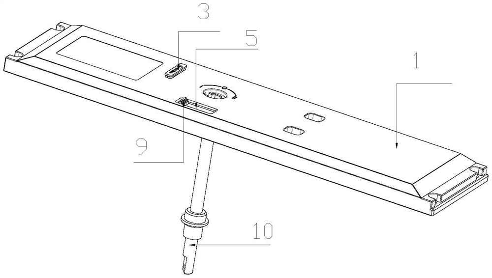
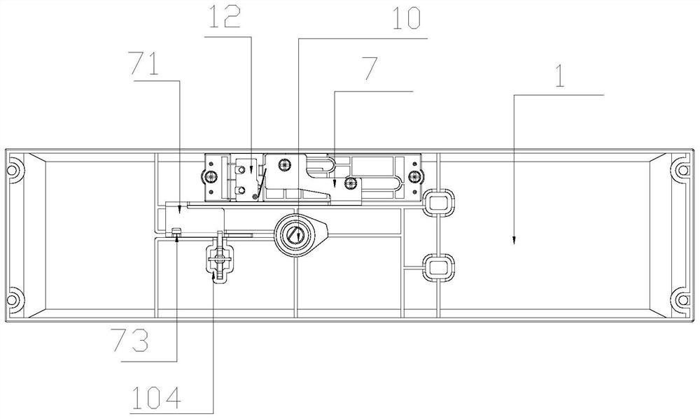
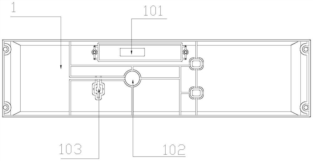
A panel is provided with a shaft hole, the shaft hole and a mandrel are concentrically arranged, the panel is further provided with a long hole, a shifting button is located in the long hole, the upper end of a cover plate is provided with a mounting groove, the upper end of the cover plate is fixedly connected to the lower end of the panel, a supporting plate is arranged in the mounting groove, the upper end of the supporting plate is fixedly connected to the lower end of the shifting button, and the upper end of the supporting plate is fixedly connected to the lower end of the shifting button. A receding hole is formed in the cover plate, the lower end of the supporting plate is fixedly connected to the upper end of the screw, the lower end of the screw is fixedly connected to the upper end of the sliding plate, the shifting button can sequentially drive the supporting plate and the sliding plate to slide, and the sliding sliding plate is of an opening and closing structure for locking the relative position of the mandrel. According to the padlock structure of the dual-power-supply change-over switch, the safety of a manual operator is guaranteed, the padlock piece can be lifted and locked only in a double-open state, the handle cannot be installed after locking, safety accidents caused by misoperation of the operator are avoided, the structure is simple, and operation is easy.

Description

technical field [0001] The invention belongs to the field of electrical switches, and in particular relates to a padlock structure of a dual power supply conversion switch. Background technique [0002] The automatic transfer switch appliance is a widely used terminal appliance. It mainly uses the controller on it to drive the electric operating mechanism to control the action of the switch, so as to connect or break the common and standby power supply, so as to ensure the safety and production of the power system. continuity. The transfer switch generally has three execution states: normal power switch on, backup power switch on and double-open. In the double-open state, the transfer switch device cuts off two power supplies at the same time to deal with equipment maintenance or other situations that require disconnection of the power supply. In this state, it is necessary to use the padlock device of the transfer switch to lock the transfer switch in the double-point stat...

Claims


Application Information

Patent Timeline
Patent Type & Authority Applications(China)
IPC IPC(8): H01H9/20
Inventor 岳鹏陈红群张晓佟
Owner SCHNEIDER WINGOAL TIANJIN ELECTRIC EQUIP
Learn More