Positioning device for upper limb surgery

A positioning device and surgical technology, applied in the direction of stereotaxic surgical instruments, etc., can solve the problem of lack of overall positioning of the palm and achieve effective positioning

Pending Publication Date: 2022-04-15
宁波路加医疗器械有限公司
View PDF1 Cites 0 Cited by
  • Summary
  • Abstract
  • Description
  • Claims
  • Application Information

AI Technical Summary

Problems solved by technology

It also has the disadvantage that only grooves corresponding to the fingers are provided on the fixing plate, and the overall positioning of the palm is sometimes lacking.

Method used


Image

  • Positioning device for upper limb surgery
  • Positioning device for upper limb surgery
  • Positioning device for upper limb surgery

Examples


Embodiment Construction

[0044] The present invention will be described in further detail below in conjunction with the accompanying drawings and specific embodiments.

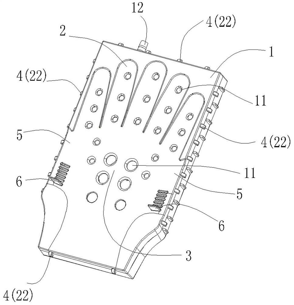
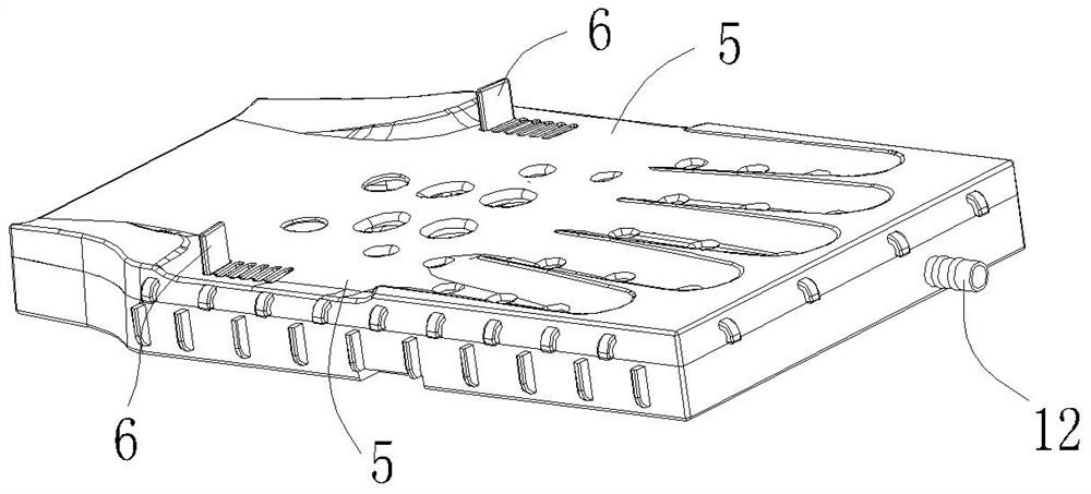
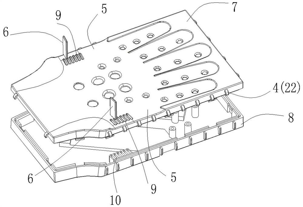
[0045] refer to Figure 1-Figure 12 , a positioning device for upper limb surgery, including a fixed plate 1, the front of the fixed plate 1 is provided with a lower concave portion adapted to the palm, and the lower concave portion includes a finger concave portion 2 corresponding to the five fingers, and a palm center Corresponding concave portion 3 under the center of the palm. When performing upper limb surgery, the palm is placed on the front of the fixed plate 1, the fingers can be located in the recess 2 of the finger, and the palm can be located in the recess 3 of the palm, so that the positioning effect of the hand is better. When in use, both sides of the palm can be positioned in the lower concave portion, even when in use, the palm can face the lower concave portion, and the back of the palm can also face the lower concav...


PUM


Abstract

The positioning device for the upper limb operation comprises a fixing plate, a downward concave part matched with the palm is arranged on the front face of the fixing plate, and the downward concave part comprises finger downward concave parts corresponding to the five fingers respectively and a palm center downward concave part corresponding to the palm center. The front face of the fixing plate is provided with the downward concave part matched with the palm, and the palm can be more effectively positioned.

Description

technical field [0001] The invention relates to a positioning device for upper limb surgery. Background technique [0002] CN1561928A discloses a hand operation supporting device, which includes a base plate, the base plate is provided with a hook, and the hook is provided with a rubber band. During the operation, the palm is placed on the base plate, and then the fingers are fixed by the rubber band. Its base plate is a flat plate, and the palm is placed on the plane and the palm is easy to move. Therefore CN 202740122 U et al. propose a hand fixation device for surgery, which includes a fixation plate and a wrist fixation belt. The fixation plate is provided with five grooves, and the grooves correspond to each finger when the palm is unfolded; the bottom surface of the groove is On the inclined surface, the lowest position of the groove corresponds to the fingertips of the fingers; the wrist fixing strap is arranged on the fixing plate. It also has the disadvantage that...

Claims


Application Information

Patent Timeline
IPC IPC(8): A61B90/14
CPCA61B90/14
Inventor 余子奇余国光胡银柯
Owner 宁波路加医疗器械有限公司
Why Eureka
Try Eureka