Supercharge Your Innovation With Domain-Expert AI Agents!

Bridge crack monitoring system

A crack system and bridge technology, which is applied in the directions of optical testing flaws/defects, chemical instruments and methods, cleaning methods and utensils, etc. Cracks, ease of movement, and the effect of expanding the shooting area

Pending Publication Date: 2022-04-22
CHINA RAILWAY BEIJING ENG GRP CO LTD +1
View PDF0 Cites 1 Cited by
  • Summary
  • Abstract
  • Description
  • Claims
  • Application Information

AI Technical Summary

Problems solved by technology

[0002] The existing bridge crack monitoring technology is to set up a platform, and the monitoring vehicle moves on the platform, so that the camera on the monitoring vehicle can shoot the bottom of the bridge deck. The platform can only provide a fixed path, which reduces the shooting area of ​​the camera. Not conducive to comprehensive monitoring of bridge deck cracks

Method used


Image

  • Bridge crack monitoring system
  • Bridge crack monitoring system
  • Bridge crack monitoring system

Examples


Embodiment 1

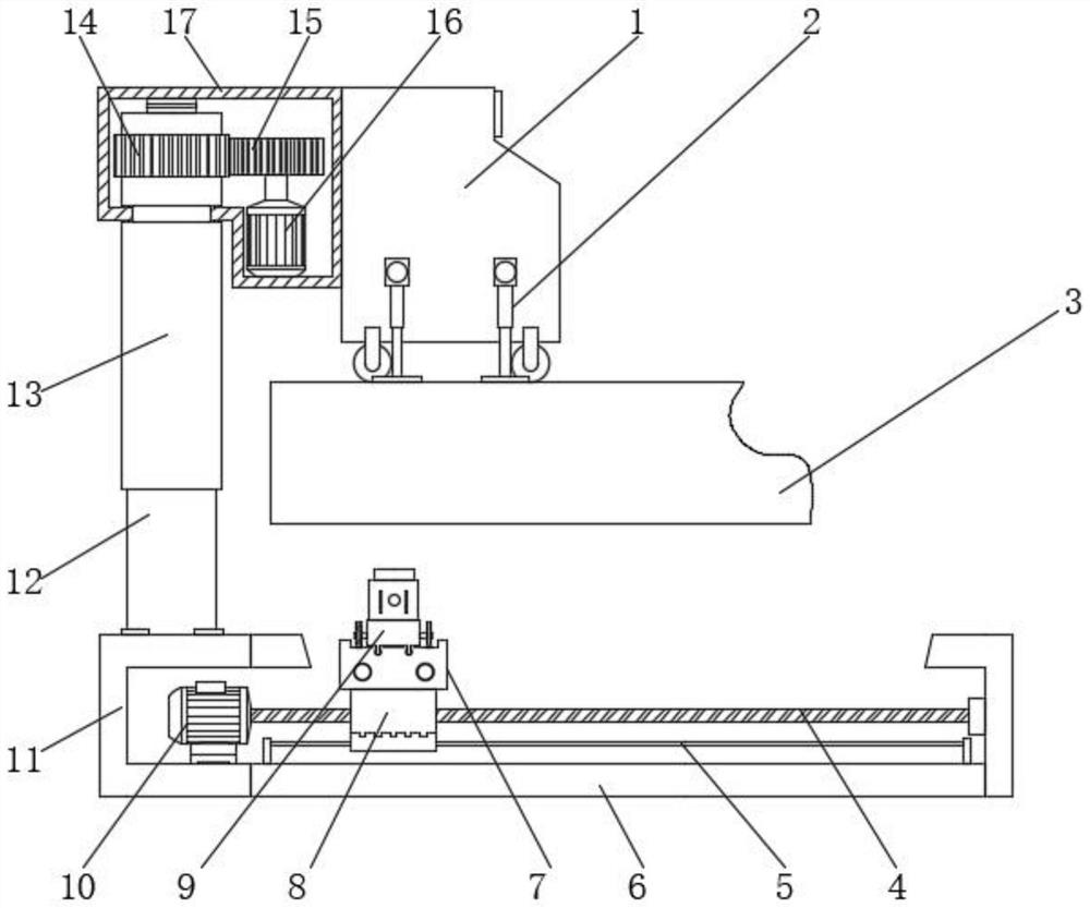
[0031] see Figure 1-6 , the present invention provides the following technical solutions: a system for monitoring bridge cracks, including a monitoring device, the monitoring device includes a monitoring platform 1, a connecting mechanism, a track mechanism, and a monitoring mechanism, the monitoring platform 1 is arranged on the top surface of the bridge deck 3, and the monitoring platform 1 A support assembly 2 for fixing is arranged on the upper surface, and an operation panel 45 is arranged on the top surface of the monitoring platform 1 .

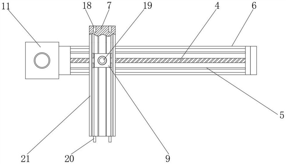
[0032] The connection mechanism includes a protective box 17 fixed on one side of the monitoring platform 1. A vertical installation shaft is movable in the protective box 17. The bottom end of the installation shaft is fixedly connected with a hydraulic cylinder 13, and the hydraulic cylinder 13 extends out of the protective box 17. One end is connected with a push rod 12, a second motor 16 is fixedly connected in the protective box ...

Embodiment 2

[0045] see Figure 7 , the difference from Example 1 is:

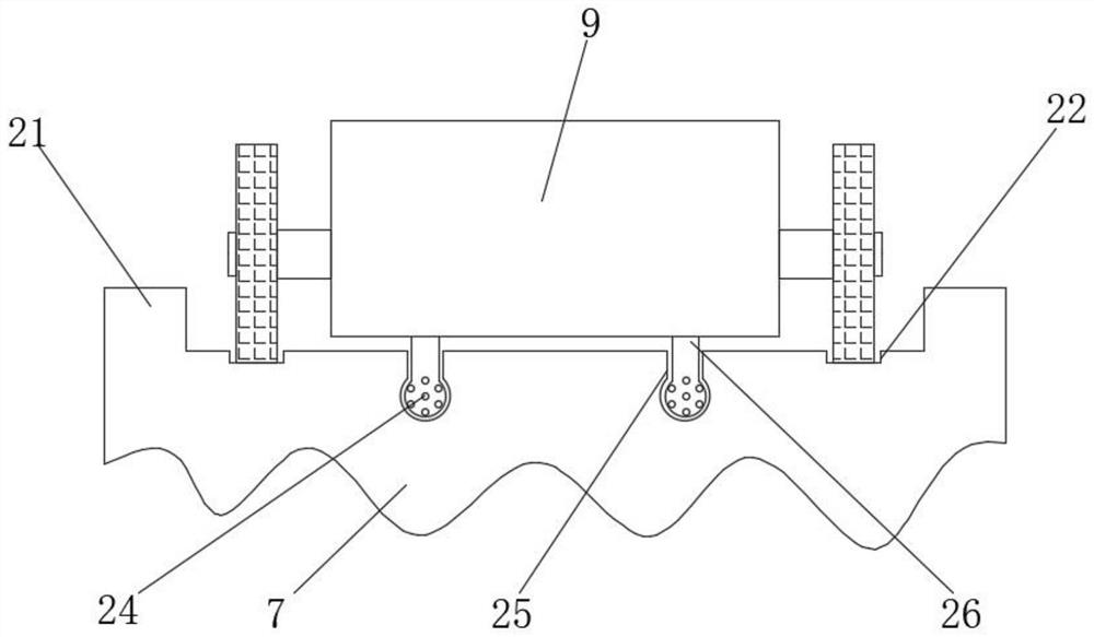
[0046] Specifically, the support assembly 2 includes a plurality of mounting plates 46 fixedly connected to the outside of the monitoring platform 1, and bolts 47 are detachably installed on the mounting plates 46, wherein the monitoring platform 1 is arranged on the external vehicle through the mounting plates 46; the fixed monitoring platform After 1, move the monitoring platform 1 through the external vehicle to achieve the effect of being convenient to move and fix the monitoring device, so that the camera 19 can take pictures of the bottom of the bridge deck 3 in an all-round way.

[0047] The working principle and application process of the present invention: move the monitoring platform 1 to the working place, fix the monitoring platform 1 through the support assembly 2, open the hydraulic cylinder 13, and the hydraulic cylinder 13 drives the sliding assembly down to the bridge deck 3 through the push rod 12 , ...


PUM


Abstract

A bridge crack monitoring system disclosed by the present invention comprises a monitoring device, the monitoring device comprises a monitoring station, a connecting mechanism, a track mechanism and a monitoring mechanism, the monitoring station is arranged on the top surface of a bridge floor, a supporting assembly for fixation is arranged on the monitoring station, and an operation panel is arranged on the top surface of the monitoring station. A sliding assembly is arranged on the side, close to the bridge floor, of the connecting frame. The sliding block and the connecting table are driven to move through the sliding assembly, the monitoring vehicle is arranged on the connecting table, and the moving path of the monitoring vehicle is perpendicular to the moving path of the sliding block, so that the moving area of the monitoring vehicle is increased, the shooting area of the camera is enlarged, and the effect of conveniently monitoring bridge cracks is achieved; the connecting tables in the multiple monitoring devices can be connected through the inserting holes and the inserting rods, the effect of further enlarging the shooting area is achieved, the guide rods used for supporting and guiding are arranged on the detection vehicle, and the guide rods move along the guide grooves.

Description

technical field [0001] The invention belongs to the technical field of bridge crack monitoring, in particular to a bridge crack monitoring system. Background technique [0002] The existing bridge crack monitoring technology is to set a platform, and the monitoring vehicle moves on the platform, so that the camera on the monitoring vehicle can shoot the bottom of the bridge deck. The platform can only provide a fixed path, which reduces the shooting area of ​​the camera. It is not conducive to the comprehensive monitoring of bridge deck cracks. Contents of the invention [0003] The object of the present invention is to provide a monitoring device that expands the path of the monitoring vehicle and improves the shooting area of ​​the camera, so as to solve the problems raised in the above-mentioned background technology. [0004] In order to achieve the above object, the present invention provides the following technical solutions: a system for monitoring bridge cracks, i...

Claims


Application Information

Patent Timeline
IPC IPC(8): G01N21/88B08B1/04B08B1/00
CPCG01N21/88B08B1/32B08B1/12
Inventor 刘长卿
Owner CHINA RAILWAY BEIJING ENG GRP CO LTD
Features
  • R&D
  • Intellectual Property
  • Life Sciences
  • Materials
  • Tech Scout
  • Unparalleled Data Quality
  • Higher Quality Content
  • 60% Fewer Hallucinations
Learn More