
Electromagnetic interference suppression circuit and method and electric equipment

An electromagnetic interference and suppression circuit technology, which is applied in the direction of electrical components, output power conversion devices, etc., can solve the problem that electromagnetic interference signals cannot obtain better interference suppression effects, and achieve good interference suppression effects

Pending Publication Date: 2022-04-22
GREE ELECTRIC APPLIANCES INC
View PDF0 Cites 0 Cited by
  • Summary
  • Abstract
  • Description
  • Claims
  • Application Information

AI Technical Summary

Problems solved by technology

[0005] An embodiment of the present invention provides an electromagnetic interference suppression circuit, method, and electrical equipment to solve the problem that the passive electromagnetic interference suppression scheme in the prior art cannot obtain better interference suppression effects for electromagnetic interference signals outside the frequency range

Method used


Image

  • Electromagnetic interference suppression circuit and method and electric equipment
  • Electromagnetic interference suppression circuit and method and electric equipment
  • Electromagnetic interference suppression circuit and method and electric equipment

Examples


Embodiment 1

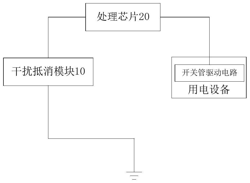
[0054] This embodiment provides an electromagnetic interference suppression circuit, which is applied to electrical equipment with a switch tube drive circuit. In this embodiment, the switch tube drive circuit can be set in the controller, wherein the switch tube drive circuit is connected to the switch The tube is used to output the switch control signal to control the on-off of the switch tube, figure 1 It is a structural diagram of an electromagnetic interference suppression circuit according to an embodiment of the present invention, such as figure 1 As shown, the above electromagnetic interference suppression circuit includes:

[0055] The interference cancellation module 10 is grounded and used to output a cancellation signal to cancel the electromagnetic interference signal generated by the switch tube drive circuit; the processing chip 20 is connected to the interference cancellation module 10 for controlling the time point of the switch control signal output by the swit...

Embodiment 2

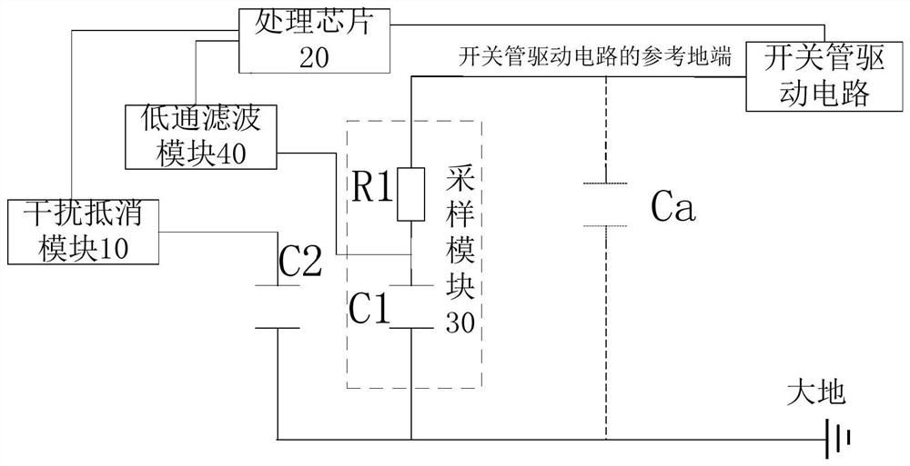
[0059] This embodiment provides another electromagnetic interference suppression circuit, figure 2 It is a structural diagram of another electromagnetic interference suppression circuit according to an embodiment of the present invention. In order to obtain the direction of the electromagnetic interference signal generated when the switch tube drive circuit outputs the switch control signal, control the direction of the cancellation signal, such as figure 2 As shown, the electromagnetic interference suppression circuit also includes:

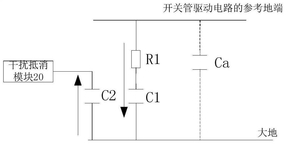
[0060] Sampling module 30, its first end is connected to the reference ground end of switch tube drive circuit, its second end is grounded, and its third end is connected to processing chip 20, is used for detecting the direction of the electromagnetic interference signal that switch tube drive circuit produces, and sends to the processing chip 20 . Such as figure 2 As shown, a parasitic capacitance Ca is generated between the reference gro...

Embodiment 3

[0086] The embodiment itself provides an electrical device, the electrical device includes a switch tube drive circuit, and also includes the electromagnetic interference suppression circuit in the above embodiment, so as to realize the suppression of the interference signal of the switch tube drive circuit, no matter the frequency range is How many can achieve active suppression of interference signals to obtain a better interference suppression effect, thereby improving the stability of electrical equipment.


PUM


Abstract

The invention discloses an electromagnetic interference suppression circuit and method and electric equipment. The electromagnetic interference suppression circuit comprises an interference offset module which is grounded and is used for outputting an offset signal so as to offset an electromagnetic interference signal generated when a switching tube driving circuit of the electric equipment outputs a switching control signal; and the processing chip is connected with the interference offset module and is used for controlling the output time of the offset signal according to the time point when the switch tube driving circuit outputs the switch control signal and controlling the direction of the offset signal according to the direction of the electromagnetic interference signal. According to the invention, active interference suppression can be carried out according to the direction of the electromagnetic interference signal and the generated time point, and a better interference suppression effect can be generated for electromagnetic interference signals with different frequencies.

Description

technical field [0001] The invention relates to the technical field of electronic power, in particular to an electromagnetic interference suppression circuit, method and electrical equipment. Background technique [0002] Electromagnetic interference includes three aspects: harmonics, conducted interference and radiated interference. For harmonic suppression, passive and active power correction circuits (PFC) are usually used. For conducted interference and radiated interference, passive However, since conducted and radiated disturbances usually have a higher frequency and are greatly affected by the power grid, electrical equipment, interference sources, parasitic parameters, and working environment, it is difficult to suppress them. [0003] The passive filtering method is a passive filtering method. When the passive filtering circuit is used as the electromagnetic interference suppression circuit to suppress conducted interference and radiation interference, the component...

Claims


Application Information

Patent Timeline
Patent Type & Authority Applications(China)
IPC IPC(8): H02M1/44H02M1/08
CPCH02M1/44H02M1/08
Inventor 杨帆贺小林李修贤
Owner GREE ELECTRIC APPLIANCES INC
Learn More