Light guide plate with multi-ring lattice points
A technology of light guide plate and dot, applied in the direction of light guide, optics, optical components, etc., can solve the problem of uneven brightness of the light guide plate, and achieve the effect of optimizing the diffusion uniformity, increasing the diffusion range, and improving the uniformity and brightness of light output.
- Summary
- Abstract
- Description
- Claims
- Application Information
AI Technical Summary
Problems solved by technology
Method used
Image

Examples
Embodiment 1
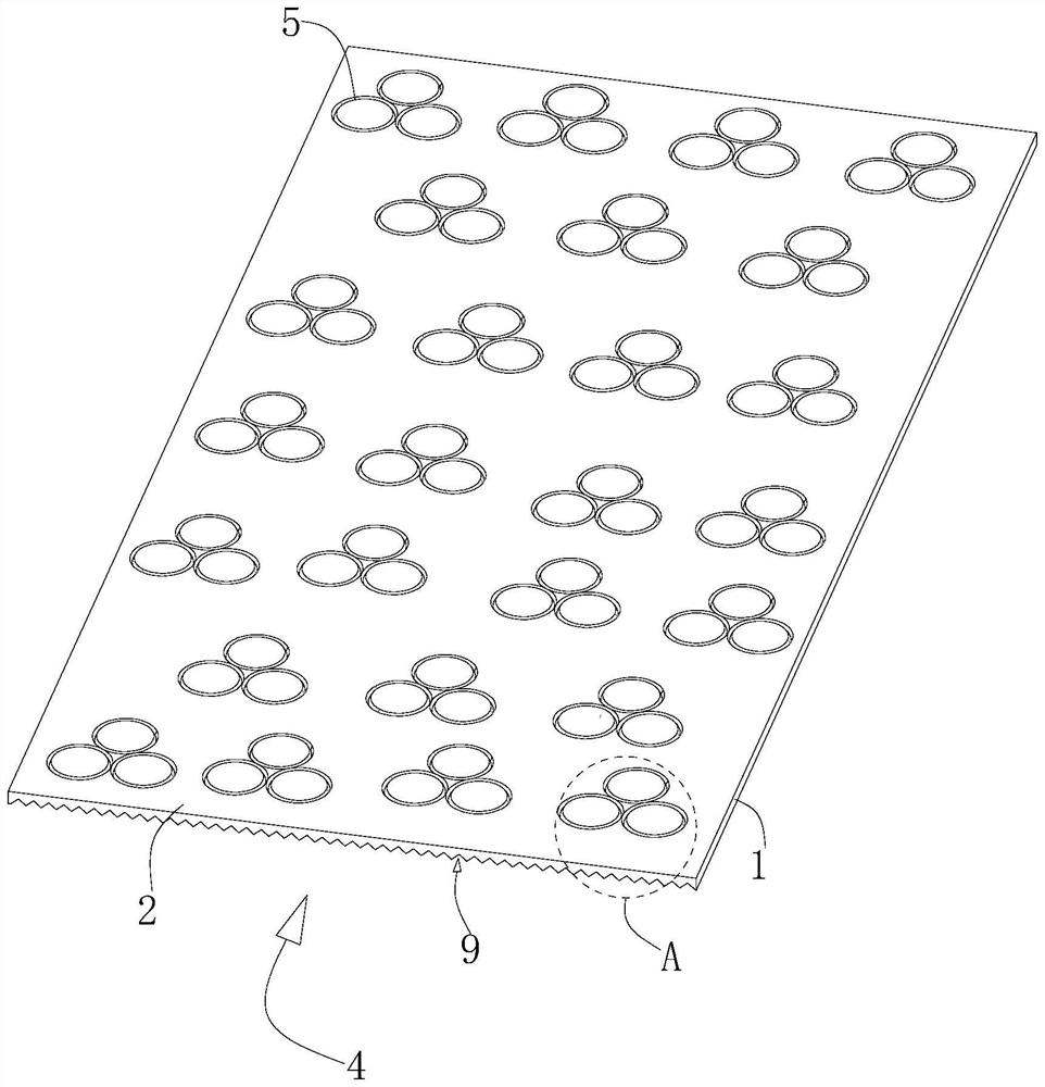
[0051] refer to figure 1 , a light guide plate with multi-ring dots, comprising a light guide plate body 1, the opposite side surfaces of the light guide plate body 1 are a dot surface 2 and a light exit surface 3, and one end of the light guide plate body 1 is set as a light source incident end 4. In this embodiment, a plurality of dot bodies 5 are arranged on the dot surface 2, and the dot bodies 5 can be arranged in a regular or random way so as to adjust the light energy distribution. In addition, the light-emitting surface 3 is provided with a light-emitting slot 9, and the light-emitting slot 9 is arranged along the direction parallel to the light source from the light source incident end 4 to the end far away from the light source incident end 4. Specifically, the light-emitting slot 9 is a V-shaped groove, and the light-emitting slot 9 9. The setting range of the depth is 20um-40um, and the setting range of the distance between the two opposite groove sides of two adja...
Embodiment 2
[0065] refer to Figure 9 , different from Embodiment 1, the network dot also includes at least three protrusions 7, at least three protrusions 7 are all arranged on the network dot surface 2, and at least three protrusions 7 and at least three first depressions There is a one-to-one correspondence between the portions 6 , and each raised portion 7 is located in the corresponding first recessed portion 6 . At least three protrusions 7 protrude toward an end away from the interior of the light guide plate body 1 . In this embodiment, the height of each protrusion 7 protruding from the screen dot surface 2 is set within a range of 10um-15um, which can effectively reduce the contact area between the reflective sheet and the light guide plate, and reduce wear on the light guide plate.
[0066] refer to Figure 10, in this embodiment, each raised portion 7 includes a first curved surface 71 and a second curved surface 72, and one side of the first curved surface 71 and the second...
Embodiment 3
[0073] refer to Figure 14 , different from Embodiment 2, a third recessed portion 20 is provided between at least three first recessed portions 6, and the third recessed portion 20 is recessed toward an end close to the interior of the light guide plate body 1, and the third recessed portion 20 The depth is higher than the depth of the second recessed part 8, and the setting range of the height difference is 2um-4um. At this time, the first recessed part 6, the second recessed part 8 and the third recessed part 20 form a step-level height difference, so that Adjust the direction of the light several times according to the transmission process of the light.
[0074] refer to Figure 15 And Fig. 16, when the third concave portion 20 is projected onto the dot plane 2, the orthographic projection surface of the third concave portion 20 is circular, and the orthographic projection surface of the third concave portion 20 and at least three first concave portions 6 The outer circu...
PUM
 Abstract
Description
Claims
Application Information
 - R&D
- Intellectual Property
- Life Sciences
- Materials
- Tech Scout
- Unparalleled Data Quality
- Higher Quality Content
- 60% Fewer Hallucinations
Browse by: Latest US Patents, China's latest patents, Technical Efficacy Thesaurus, Application Domain, Technology Topic, Popular Technical Reports.
© 2025 PatSnap. All rights reserved.Legal|Privacy policy|Modern Slavery Act Transparency Statement|Sitemap|About US| Contact US: help@patsnap.com