Medical in-ear ointment smearing equipment

A technology of ointment and equipment, which is applied in the field of medical ointment application equipment in the ear, can solve the problem of manpower consumption, and achieve the effect of avoiding easy leakage

Pending Publication Date: 2022-05-06
刘华
View PDF1 Cites 0 Cited by
  • Summary
  • Abstract
  • Description
  • Claims
  • Application Information

AI Technical Summary

Problems solved by technology

[0004] We have designed an automatic push medical ear ointment application equipment to overcome the labor-intensive effect of manually pushing the medicine during the application process of the existing medicine application equipment

Method used


Image

  • Medical in-ear ointment smearing equipment
  • Medical in-ear ointment smearing equipment
  • Medical in-ear ointment smearing equipment

Examples


Embodiment 1

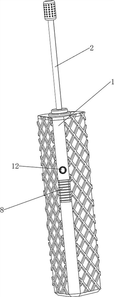
[0037] A kind of medical ear ointment smearing equipment, now refer to Figure 1-7, including a housing 1, a first guide tube 2, a second guide tube 21, a discharge head 22, a first support frame 3, a medicine box 4, a first push plate 5, a second support frame 6, and a drug feeding Mechanism 7 and tonic mechanism 8, a medicine box 4 is arranged in the middle of the housing 1, and the medicine box 4 is used to contain ointment, a box opening is provided on the upper left side of the medicine box 4, and a first support frame is provided on the inner upper side of the housing 1 3. A second guide tube 21 is provided between the upper side of the medicine box 4 and the first support frame 3. The upper side of the second guide tube 21 is rotatably provided with a first guide tube 2. The first guide tube 2 is connected to the The first support frame 3 is connected to the housing 1 in a rotational manner, the upper side of the first guide pipe 2 is provided with a discharge head 22, ...

Embodiment 2

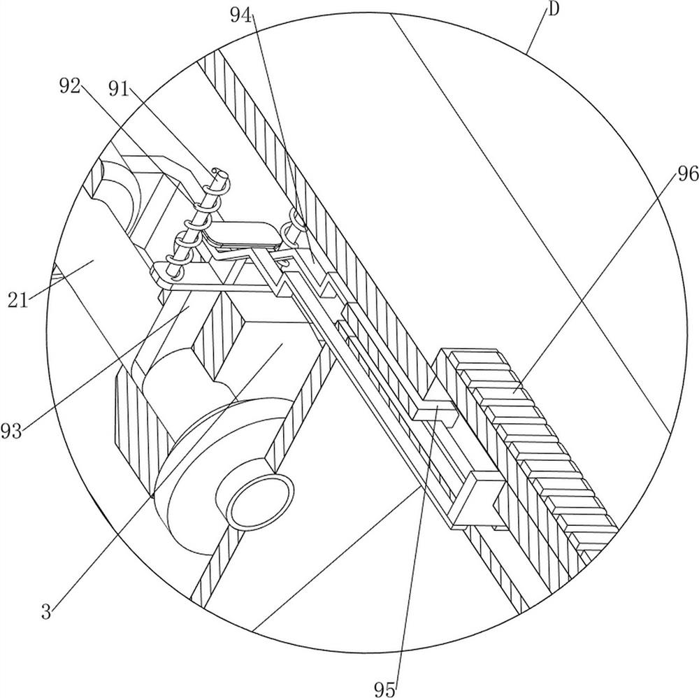
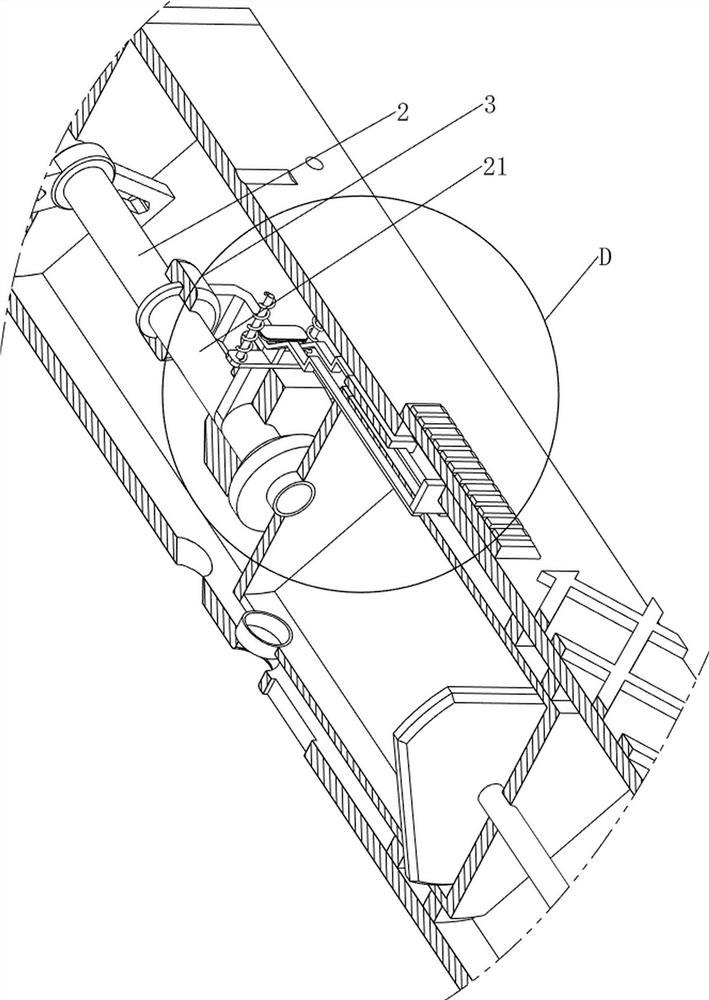
[0042] On the basis of embodiment 1, now refer to Figure 5 , Figure 7 , Figure 11 , Figure 12 and Figure 15 , also includes a partition mechanism 9, the partition mechanism 9 includes a second slide bar 91, a second spring 92, a second baffle plate 93, a wedge block 94, a limit block 95 and a second slide block 96, the right part of the medicine box 4 The upper side is welded with a limit block 95, and the front and rear sides of the limit block 95 are slidingly provided with a wedge block 94. The wedge block 94 is slidably connected with the medicine box 4. The front and rear sides of the space are provided with a second slide bar 91, and a second baffle plate 93 is slidably provided between the two second slide bars 91. Sliding connection, the wedge block 94 is slidably connected with the second baffle plate 93, and the second spring 92 is connected between the front and rear sides of the right part of the second baffle plate 93 and the housing 1, and the second spr...


PUM


Abstract

The invention relates to smearing equipment, in particular to medical in-ear ointment smearing equipment. The invention provides medical in-ear ointment smearing equipment capable of being automatically pushed. Medical in-ear ointment smearing equipment comprises a shell, a first flow guide pipe, a second flow guide pipe, a discharging head, a first supporting frame, an ointment box and the like. A pesticide box is arranged in the middle in the shell, a first supporting frame is arranged on the upper side in the shell, a second flow guide pipe is arranged between the upper side of the pesticide box and the first supporting frame, a first flow guide pipe is rotationally arranged on the upper side of the second flow guide pipe and rotationally connected with the first supporting frame and the shell, and a discharging head is arranged on the upper side of the first flow guide pipe. A first motor is started by people, and an output shaft of the first motor rotates to drive a lead screw to rotate, so that a second push plate moves downwards, a first push plate pushes ointment downwards, the ointment flows into a discharging head through a second flow guide pipe and a first flow guide pipe, and the automatic pushing effect is achieved.

Description

technical field [0001] The invention relates to a smearing device, in particular to a medical ear ointment smearing device. Background technique [0002] For patients with inflammation in the ear canal, it is necessary to apply medicine to the affected part during the treatment process, so it is necessary to design a smearing device. [0003] Patent application: CN212346910U, with a publication date of 20210115, which discloses an ear canal drug application device, through which the ear canal drug application device includes a drug application tube, and the drug application tube includes a connected hose and a hard tube, and the hard tube The end away from the hose is connected with a blower, the side wall of the hose is provided with a medicine outlet, the side wall of the hard tube away from the end of the hose is connected with a medicine feeding device, and the medicine feeding device includes a medicine feeding device. A drug tube, one end of the drug feeding tube is i...

Claims


Application Information

Patent Timeline
IPC IPC(8): A61M31/00A61F11/00A61M3/02
CPCA61M31/00A61F11/00A61M3/0279A61M2210/0662A61M2210/005
Inventor 刘华
Owner 刘华
Why Eureka
Try Eureka