A missile hanger device

A technology of missiles and substrates, which is applied in the direction of equipment for cargo transportation, etc., can solve the problems of increased supporting force, limited circumferential rotation angle of missiles, small contact surface, etc., and achieve the effect of increasing stability

Active Publication Date: 2022-06-21
北京航天和兴科技股份有限公司
View PDF1 Cites 0 Cited by
  • Summary
  • Abstract
  • Description
  • Claims
  • Application Information

AI Technical Summary

Problems solved by technology

[0004] The above invention has some deficiencies during use. For example, after using the bracket to place the missile, push the bottom end of the bracket through the first lead screw and the second lead screw, so that the bracket and the missile will rotate in a circumferential direction as a whole. , where the circumferential rotation angle of the missile is limited, which cannot meet the needs of use. In addition, the positioning handle is used for positioning and clamping on the side of the missile. The contact surface is small. After the axial rotation is adjusted, the positioning handle is located under the side of the missile. The supporting force between the positioning handles will become larger, causing the surface of the missile to be concave

Method used

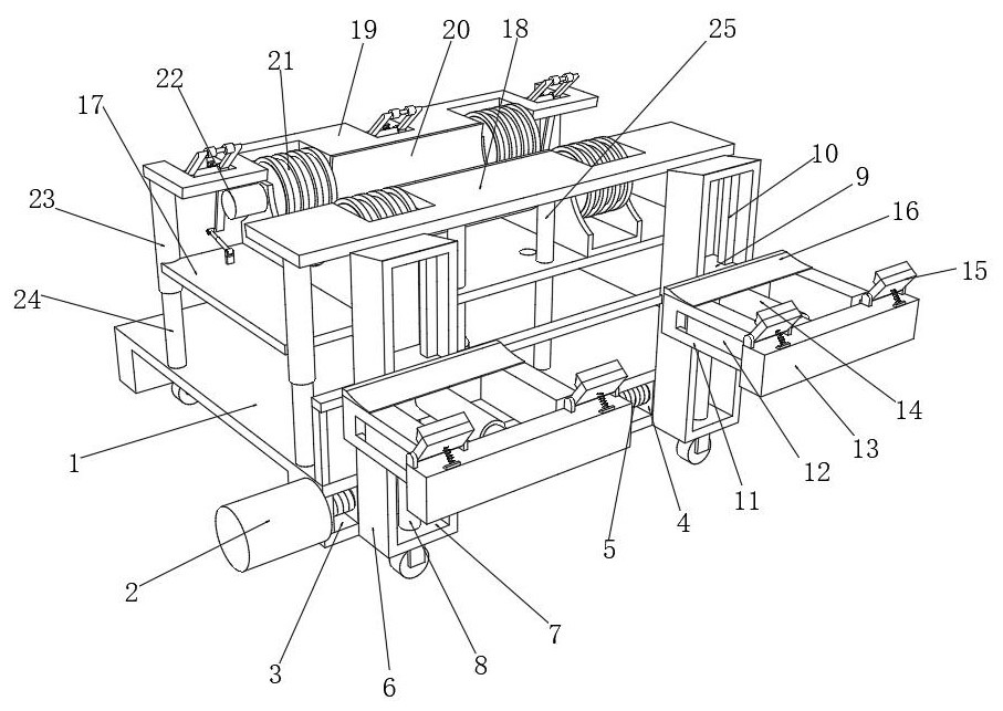
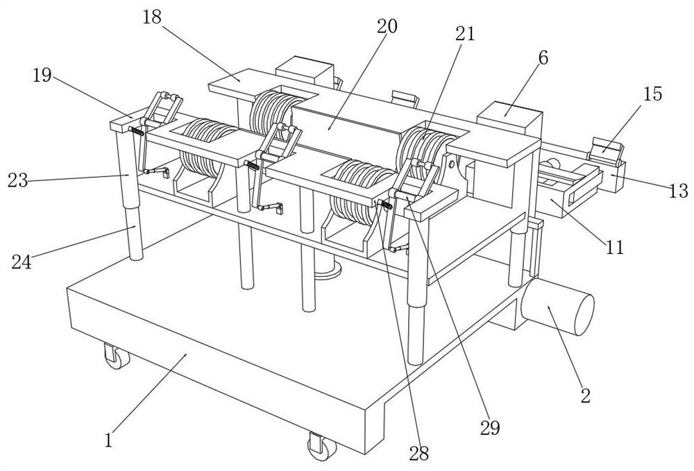
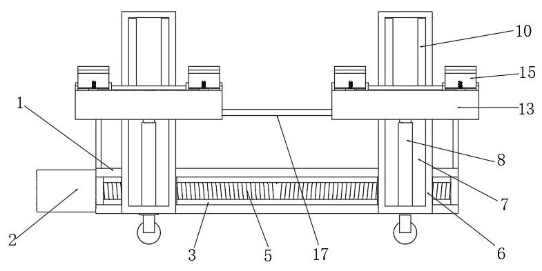

Image

  • A missile hanger device
  • A missile hanger device
  • A missile hanger device

Examples


Embodiment Construction

[0031] The technical solutions of the present invention will be clearly and completely described below with reference to the accompanying drawings. Obviously, the described embodiments are a part of the embodiments of the present invention, but not all of the embodiments.

[0032] The components of the embodiments of the invention generally described and shown in the drawings herein may be arranged and designed in a variety of different configurations. Thus, the following detailed description of the embodiments of the invention provided in the accompanying drawings is not intended to limit the scope of the invention as claimed, but is merely representative of selected embodiments of the invention.

[0033] Based on the embodiments of the present invention, all other embodiments obtained by those of ordinary skill in the art without creative efforts shall fall within the protection scope of the present invention.

[0034] In the description of the present invention, it should b...


PUM


Abstract

The invention discloses a missile hanger device, which relates to the technical field of assembly equipment. Two lifting assemblies, the lifting assembly is equipped with a supporting assembly, the top of the base plate is installed with a hydraulic cylinder, the top of the hydraulic cylinder is fixed with a lifting platform, and the top of the lifting platform is fixed with a circumferential adjustment mechanism, the two sides of the circumferential adjustment mechanism are respectively provided with a first top plate and a second top plate, a U-shaped plate is fixed between the first top plate and the second top plate, and there are multiple There is a notch, and a fixed shaft is rotatably installed in the notch. The invention can drive the missile to complete the whole-circle direction adjustment work, meet the angle adjustment requirements for the installation work of the missile, and can also use the supporting wheels to perform limit support work on the side of the missile after the loading of the missile is completed.

Description

technical field [0001] The invention relates to the technical field of assembly equipment, in particular to a missile hanger device. Background technique [0002] The application fields of pylons are very wide, whether it is in the field of daily life or even in the field of military industry. At present, missile pylons are often equipped on the mounting equipment of aircraft weapons, but most of the common pylons are A simple bracket cannot effectively adjust the circumferential position of the missile, which brings inconvenience to the operator and has corresponding limitations. [0003] The existing Chinese utility model patent with publication number CN210852937U discloses a missile hanger device, comprising a mounting base plate and a hanger main body, the hanger main body is fixedly connected to the bottom side mounting base plate through a wing nut, and the hanger main body is fixedly connected with the bottom side mounting base plate. A bracket is installed on the u...

Claims


Application Information

Patent Timeline
Patent Type & Authority Patents(China)
IPC IPC(8): B64F1/32
CPCB64F1/32
Inventor 闫振强张赢朱文飞
Owner 北京航天和兴科技股份有限公司
Why Eureka
Try Eureka